
During the last eight articles we have covered different aspects of facility information management in a real-world project. In this article I will focus on a facility’s configuration management.
If you would like to read previous chapters first before we take a deeper dive into facility configuration management, you can find them all here: Archive
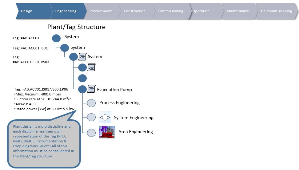
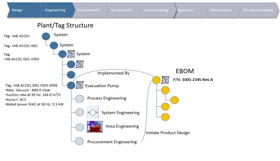
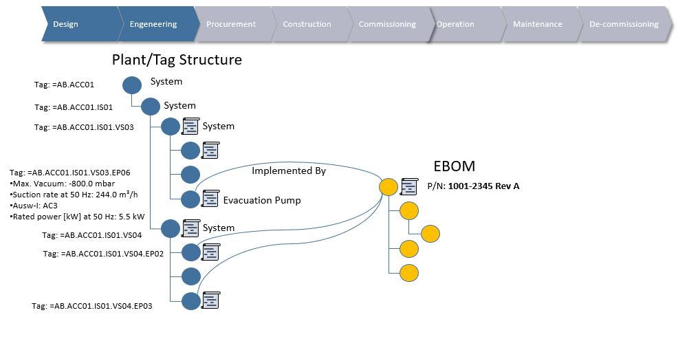
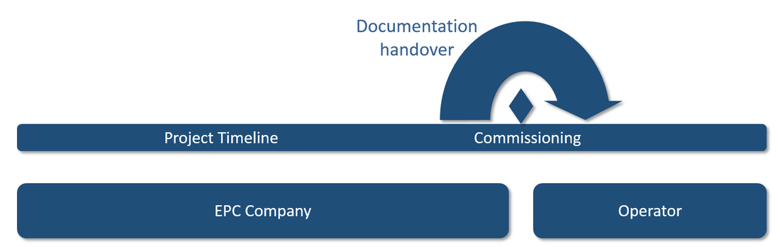
In my view there are two important parts to facility configuration management. One is the management of changes, traceability and control of the individual information structures we’ve talked about in previous chapters, so, how is the information in the Functional Breakdown Structure, Location Breakdown Structure, product designs (EBOM) and installed asset information managed when changes needs to be made.
As an example, a system design for a water-cooling system in the Functional Breakdown Structure will most likely undergo several design changes during its lifetime, even after it has been taken into operation. Such design changes will lead to work performed on the already installed assets in the facility. Either in the form of re-calibration of existing assets, replacement of assets or even new installations and subsequent commissioning of those installations.
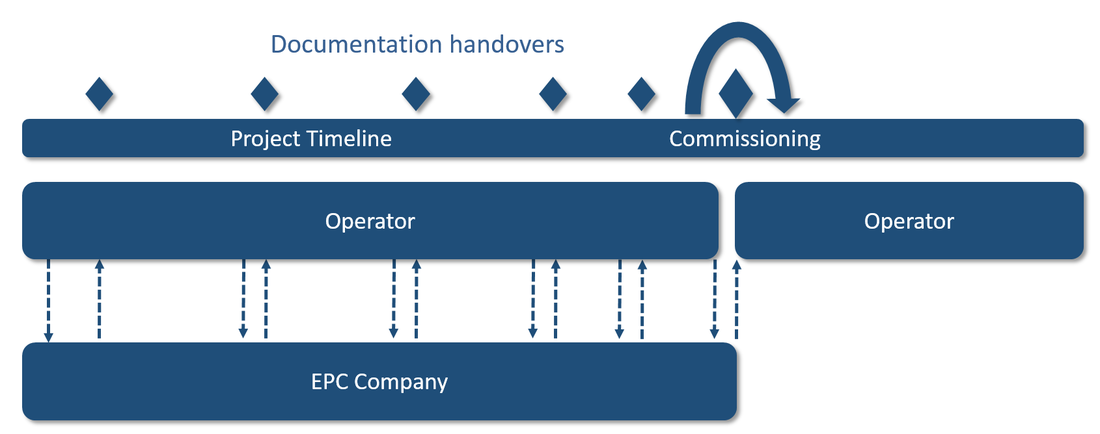
This leads us nicely to the second part of facility configuration management, because as the Functional Breakdown Structure (the facility design) evolves during the lifetime of a facility, we need to be able to identify at least the following:
This all means that it is not enough to have control of all changes. A possibility must also exist to be able to say what the exact initially agreed design requirements were, what the As-Built was like (combination of design requirement and physically installed asset information to see that what was installed is in accordance with the design requirements) AND how the assets have evolved as a result of operations and maintenance work since initial commissioning (As-Maintained or As-Operated).
Having control of this is extremely important, both to be in compliance with regulatory requirements if an accident were to occur or in the event of an audit, but also for analysis and tracking of the facility’s well being and effective maintenance.
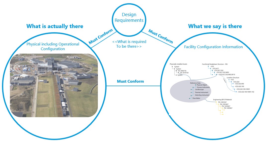
The figure below is loosely borrowed from an excellent publication from IAEA (International Atomic Energy Agency) on configuration management in nuclear plants ( IAEA-TECDOC-1335)
If you would like to read previous chapters first before we take a deeper dive into facility configuration management, you can find them all here: Archive
In my view there are two important parts to facility configuration management. One is the management of changes, traceability and control of the individual information structures we’ve talked about in previous chapters, so, how is the information in the Functional Breakdown Structure, Location Breakdown Structure, product designs (EBOM) and installed asset information managed when changes needs to be made.
As an example, a system design for a water-cooling system in the Functional Breakdown Structure will most likely undergo several design changes during its lifetime, even after it has been taken into operation. Such design changes will lead to work performed on the already installed assets in the facility. Either in the form of re-calibration of existing assets, replacement of assets or even new installations and subsequent commissioning of those installations.
This leads us nicely to the second part of facility configuration management, because as the Functional Breakdown Structure (the facility design) evolves during the lifetime of a facility, we need to be able to identify at least the following:
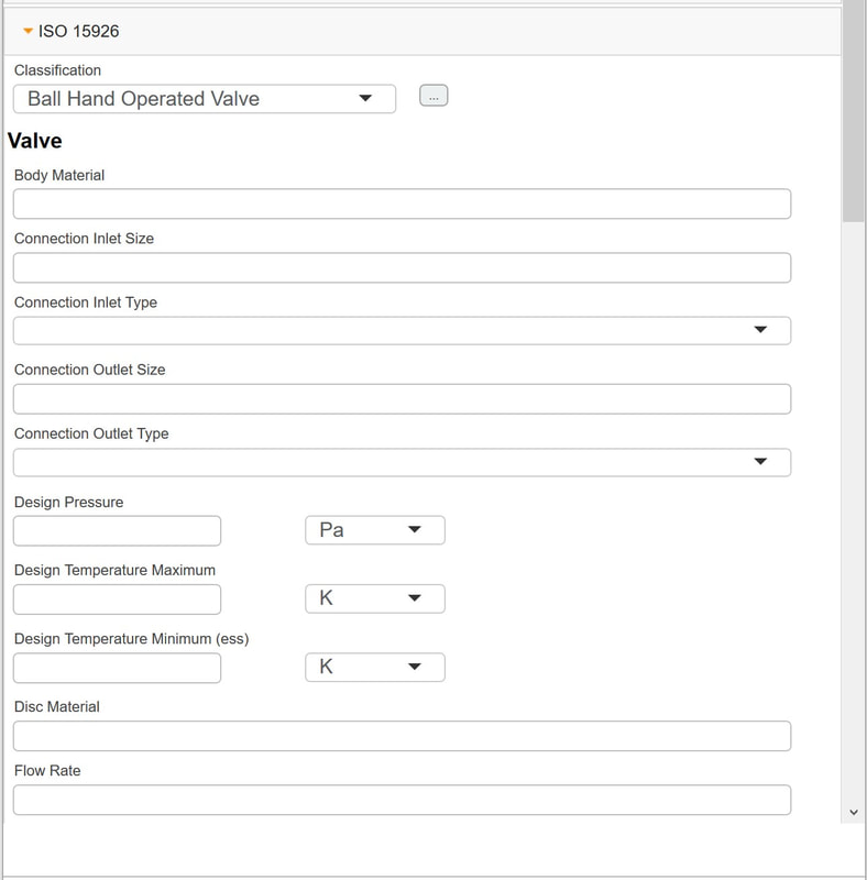
- What the facility’s design requirements originally were (As-Designed)
- What we installed in the facility to fulfill the design requirements (assets) including operational configuration information (As-Built)
- What has been done to the installed assets after commissioning of the facility (As-Maintained or As-Operated)
This all means that it is not enough to have control of all changes. A possibility must also exist to be able to say what the exact initially agreed design requirements were, what the As-Built was like (combination of design requirement and physically installed asset information to see that what was installed is in accordance with the design requirements) AND how the assets have evolved as a result of operations and maintenance work since initial commissioning (As-Maintained or As-Operated).
Having control of this is extremely important, both to be in compliance with regulatory requirements if an accident were to occur or in the event of an audit, but also for analysis and tracking of the facility’s well being and effective maintenance.
The figure below is loosely borrowed from an excellent publication from IAEA (International Atomic Energy Agency) on configuration management in nuclear plants ( IAEA-TECDOC-1335)
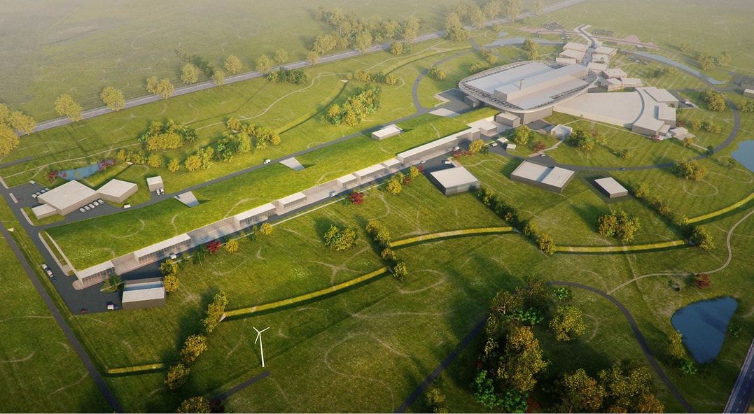
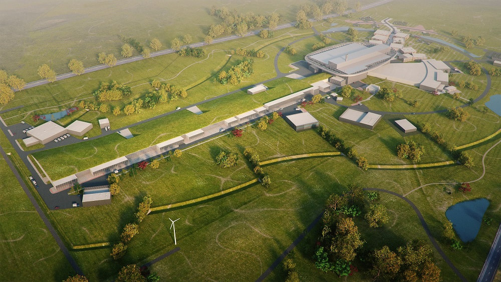
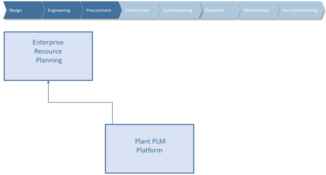
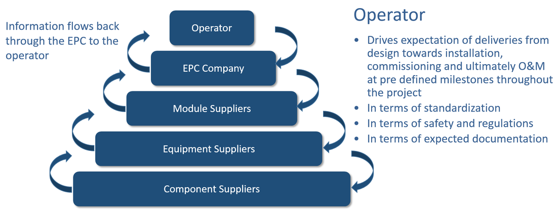
Figure 1: Image used in infographic is courtesy of European Spallation Source ERIC
Although the publication is old (from 2003), it explains very well what information needs to be controlled (even if it was document centric back then). I have translated it to what it will mean from a structured data management perspective. In essence: Design requirements must conform to what we say is there, and what we say is there includes the information stored in a functional breakdown structure, location breakdown structure, associated product data and all data regarding the installed asset including operational configuration information and maintenance information.
But hang on, that is only the right-hand part of the picture!
Exactly, because we also need to be able to prove that what we say is there conforms to what is actually there physically on site in the facility, and that what is physically there on site conforms to the design requirements.
This means that work processes must be in place from the facility owner side to assure that:
How can this be achieved?
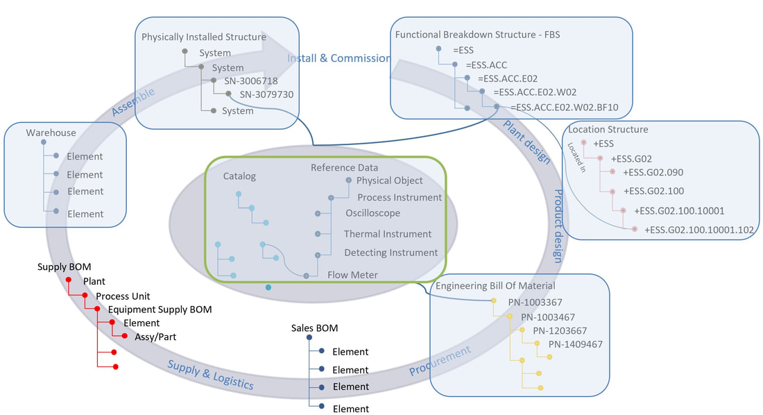
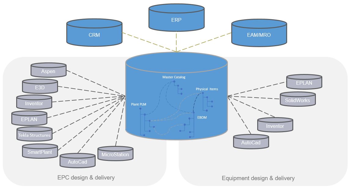
If facility data is structured and connected like in the previous article series of “PLM tales from a true mega-project” and Plant Information Management (see Archive), configuration management becomes a lot easier, but is still by all means not trivial.
Although the publication is old (from 2003), it explains very well what information needs to be controlled (even if it was document centric back then). I have translated it to what it will mean from a structured data management perspective. In essence: Design requirements must conform to what we say is there, and what we say is there includes the information stored in a functional breakdown structure, location breakdown structure, associated product data and all data regarding the installed asset including operational configuration information and maintenance information.
But hang on, that is only the right-hand part of the picture!
Exactly, because we also need to be able to prove that what we say is there conforms to what is actually there physically on site in the facility, and that what is physically there on site conforms to the design requirements.
This means that work processes must be in place from the facility owner side to assure that:
- Design data, installed assets and all associated information conform all of the time
- All changes are authorized
- Conformance can be verified
How can this be achieved?
If facility data is structured and connected like in the previous article series of “PLM tales from a true mega-project” and Plant Information Management (see Archive), configuration management becomes a lot easier, but is still by all means not trivial.
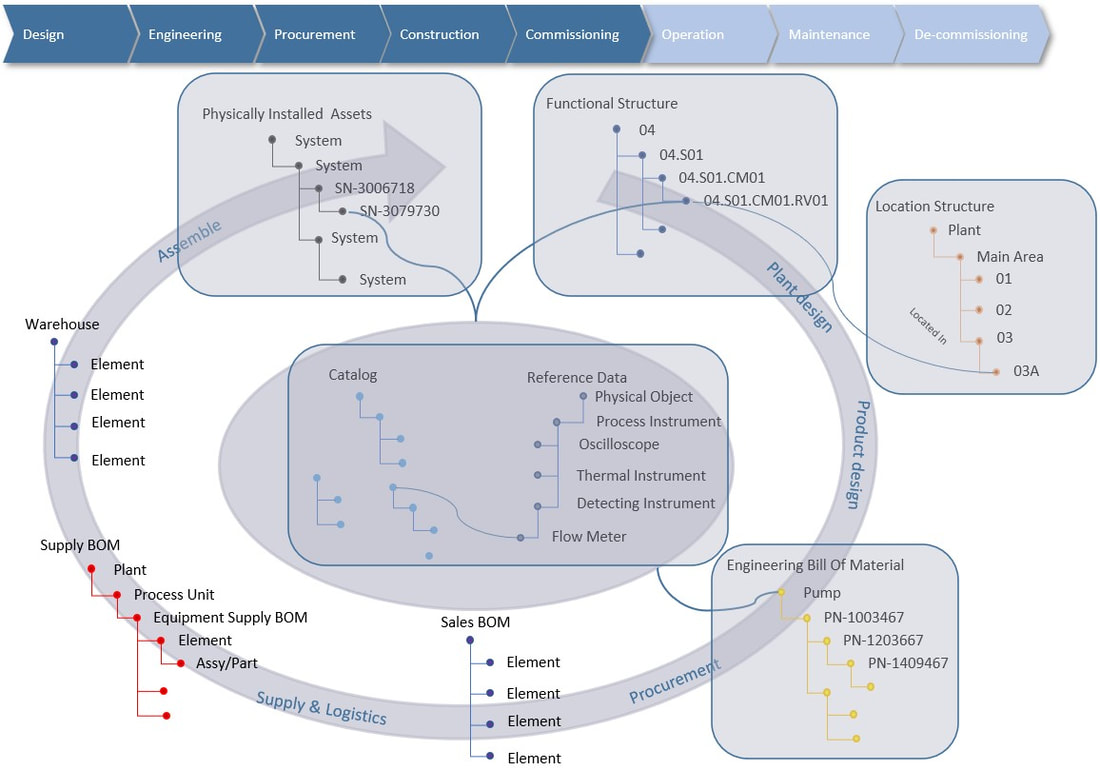
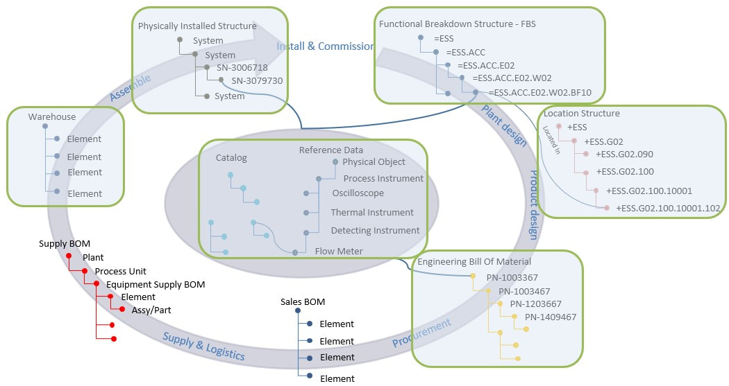
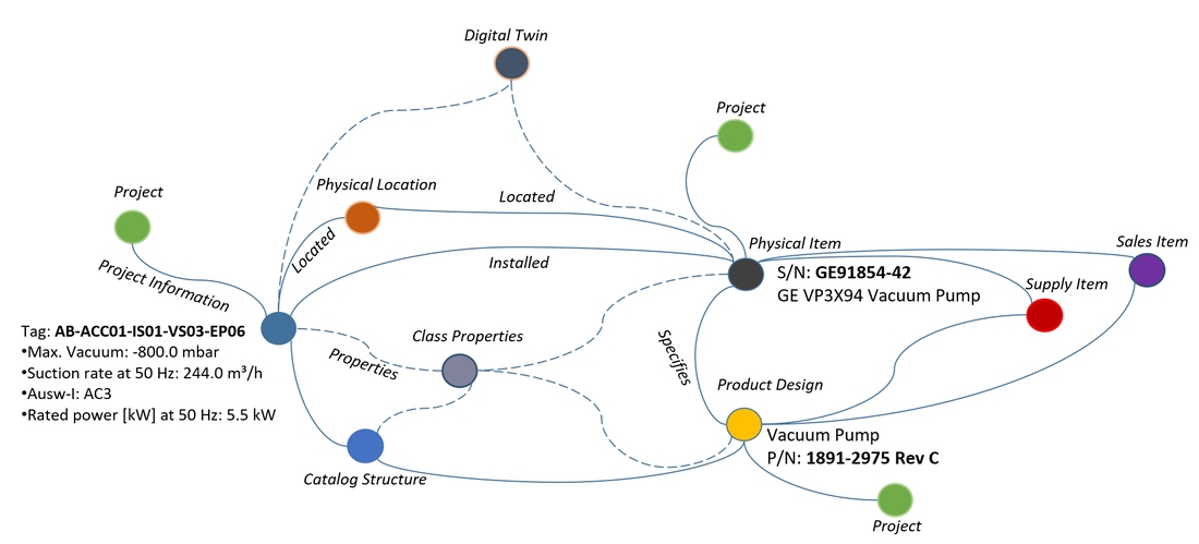
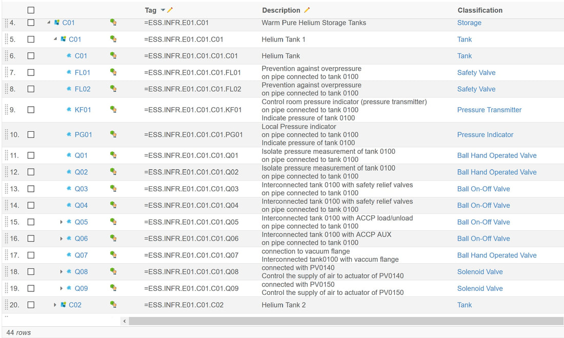
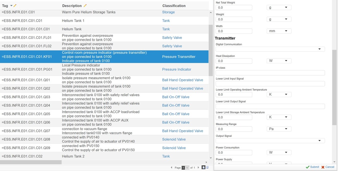
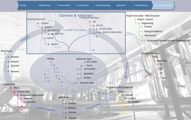
Figure 2: Important structured information for Configuration Management
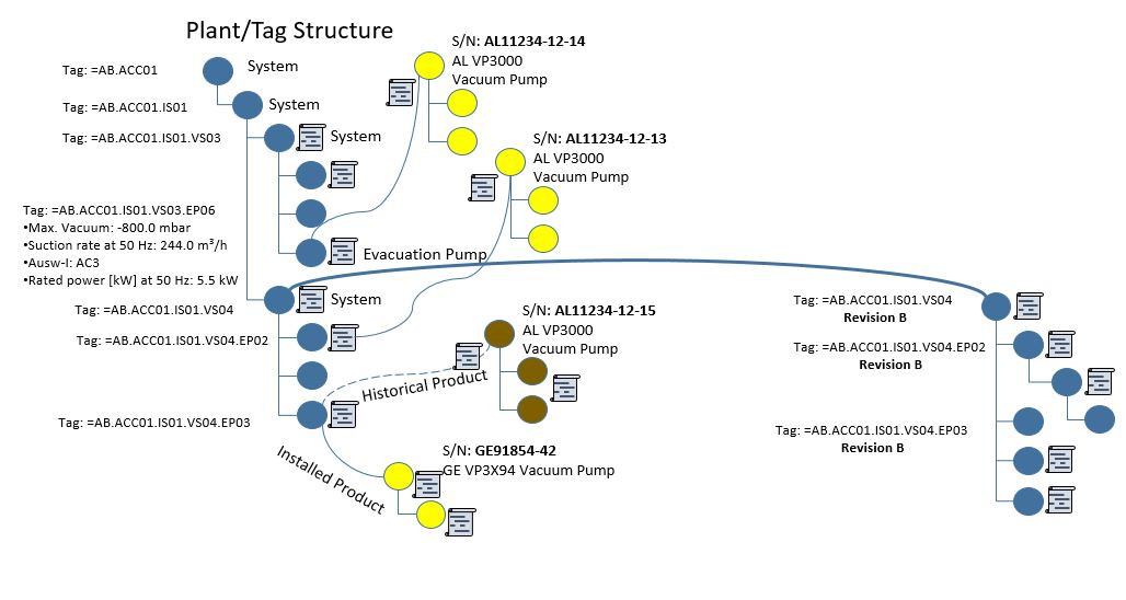
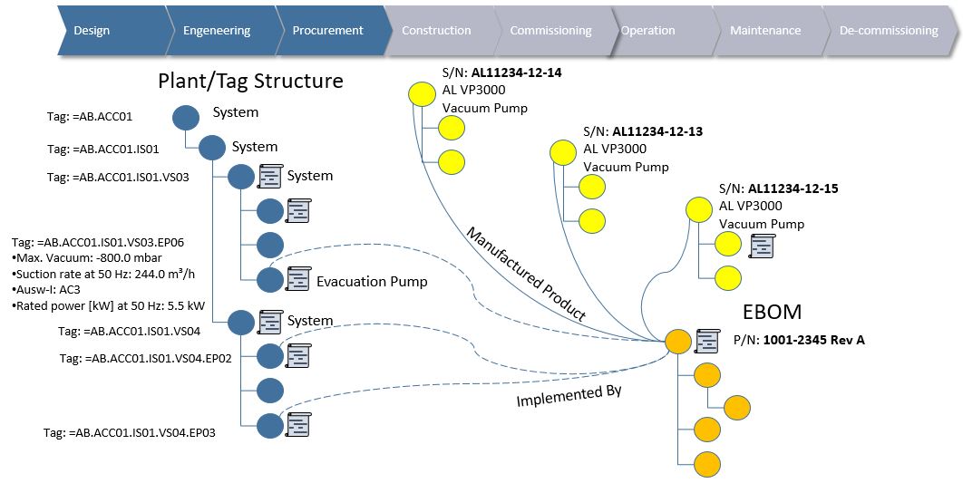
As the facility design (Functional Breakdown Structure) evolves over time, it must be possible to make “snapshots” or rather baselines of each individual system design within the functional breakdown structure when they reach sufficient maturity (released from design perspective to manufacturing). These “snapshots”, when performed on each and every system in the facility will gradually populate a complete As-Designed baseline of the full facility design.
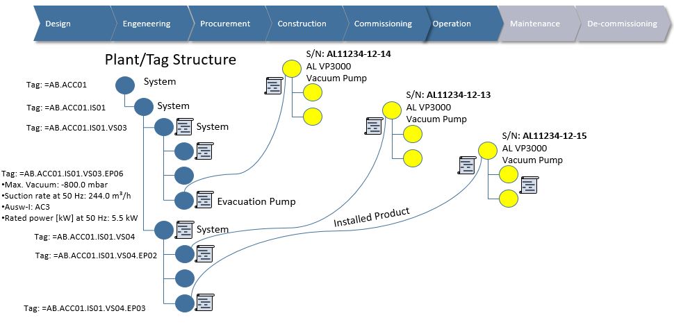
The exact same mechanism must be in place to create an As-Built, but here the installed asset information also needs to be included as well as any “red-line drawings” or deviation from the As-Designed information. Such deviations, if managed correctly, has already introduced changes in the functional breakdown structure via a change order which renders it different compared to the As-Designed baseline.
The new incremental baselines of designed systems including design changes made during installation together with actually installed asset information, calibration, certificates and traceability of performed work altogether forms the As-Built baseline.
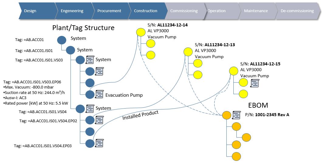
When such capabilities are in place, we are able to say exactly what the As-Designed looked like and what the As-Built was like, and it allows for comparison between the two in order to determine what the differences were, why they occurred and who authorized them.
With such capabilities one could also create other forms of baselines if needed, like As-Installed, As-Commissioned etc.
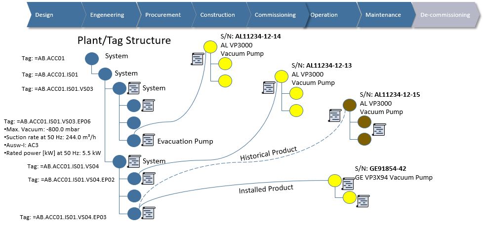
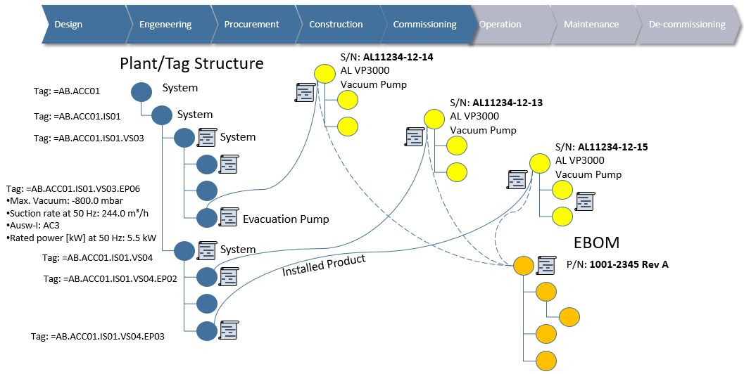
The As-Maintained or As-Operated would not really be a baseline, but rather the current state of the connected information structures at any given time during operations. However, it must be possible to compare the current state of the connected information with both the As-Built and the As-Designed baselines. It would also be advisable to perform baselines or snapshots of systems at intervals to be able to say something about how the facility has evolved, and especially prior to any large modifications to the facility.
Bjorn Fidjeland
As the facility design (Functional Breakdown Structure) evolves over time, it must be possible to make “snapshots” or rather baselines of each individual system design within the functional breakdown structure when they reach sufficient maturity (released from design perspective to manufacturing). These “snapshots”, when performed on each and every system in the facility will gradually populate a complete As-Designed baseline of the full facility design.
The exact same mechanism must be in place to create an As-Built, but here the installed asset information also needs to be included as well as any “red-line drawings” or deviation from the As-Designed information. Such deviations, if managed correctly, has already introduced changes in the functional breakdown structure via a change order which renders it different compared to the As-Designed baseline.
The new incremental baselines of designed systems including design changes made during installation together with actually installed asset information, calibration, certificates and traceability of performed work altogether forms the As-Built baseline.
When such capabilities are in place, we are able to say exactly what the As-Designed looked like and what the As-Built was like, and it allows for comparison between the two in order to determine what the differences were, why they occurred and who authorized them.
With such capabilities one could also create other forms of baselines if needed, like As-Installed, As-Commissioned etc.
The As-Maintained or As-Operated would not really be a baseline, but rather the current state of the connected information structures at any given time during operations. However, it must be possible to compare the current state of the connected information with both the As-Built and the As-Designed baselines. It would also be advisable to perform baselines or snapshots of systems at intervals to be able to say something about how the facility has evolved, and especially prior to any large modifications to the facility.
Bjorn Fidjeland


 RSS Feed
