

Image courtesy of ESS Spatial Integration Team
In the past chapters I’ve talked an awful lot about structured data and information structures, and yes, in my view this is very important as it is the very essence to obtain effective Plant Lifecycle Management, however in this chapter let’s take breather from the data structures and have a look at how ESS manages the aspect of space management (which is also a structure….. Of course I almost hear you say, but it looks a lot shinier, and by the way, yes it is connected to the tag structure (FBS) and the other information structures).
At ESS there is a team headed by Fabien Rey, responsible for Spatial Integration which includes an all discipline 3D master-model called the EPL (ESS Plant Layout) of the entire facility.
So, what is this Spatial Integration?
It is defined as configuration management of the space available. This means that everything that is designed and that will go into the facility and will occupy space, must have received an initial space claim which is then refined throughout the engineering process. This is true for all disciplines from conventional building, machine systems, product engineering, plant & process to electrical.
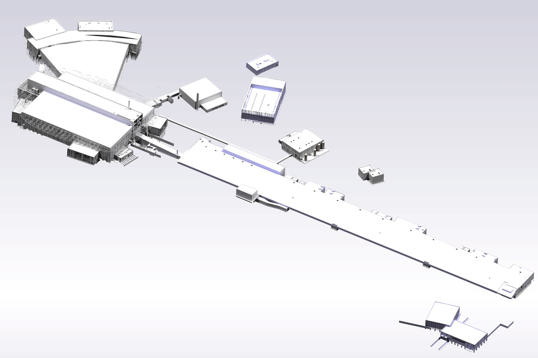
Image courtesy of ESS Spatial Integration Team
When examining the EPL from afar, it looks pretty much like what you would expect from any architectural model, but when focusing on the machine aspects in the facility it gets more interesting, however as ESS is a huge facility, so, still not much detail
When examining the EPL from afar, it looks pretty much like what you would expect from any architectural model, but when focusing on the machine aspects in the facility it gets more interesting, however as ESS is a huge facility, so, still not much detail
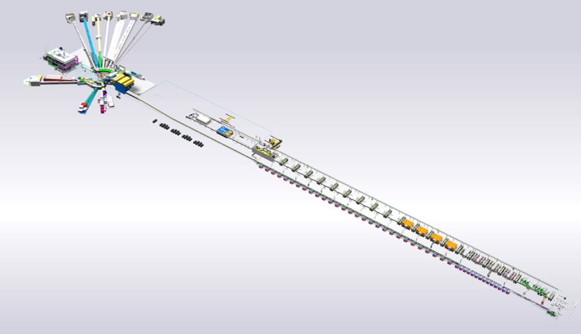
Image courtesy of ESS Spatial Integration Team
Let’s zoom in on the tiny little area at the bottom right corner, which is where the proton beam starts its journey towards the target to create spallation of neutrons.
Let’s zoom in on the tiny little area at the bottom right corner, which is where the proton beam starts its journey towards the target to create spallation of neutrons.
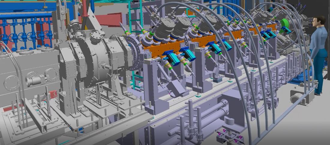
Image courtesy of ESS Spatial Integration Team
Here we get a taste for the enormous level of detail we are talking about.
The person to the right is to get a feel for the scale. This picture only shows the first few meters of the 650-meter-long accelerator.
The image is from the Virtual Reality room at ESS. The VR room is used for several different purposes, but among them, multi-discipline reviews for everything from design to installation and commissioning activities.
Let's look the other way
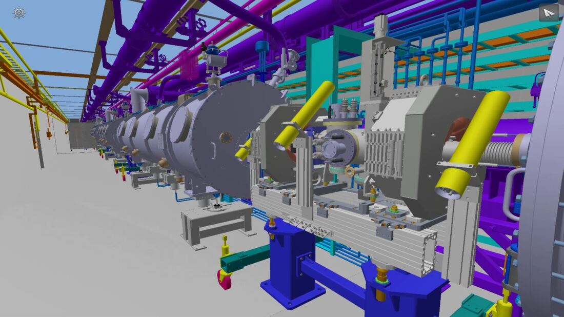
Image courtesy of ESS Spatial Integration Team
The next picture is taken, not from the VR room, but still the same EPL.
This time from a different software with a slightly different purpose. What is unique in my experience is that it is the same model, under configuration control, loaded into different environments for different purposes.
The next picture is taken, not from the VR room, but still the same EPL.
This time from a different software with a slightly different purpose. What is unique in my experience is that it is the same model, under configuration control, loaded into different environments for different purposes.
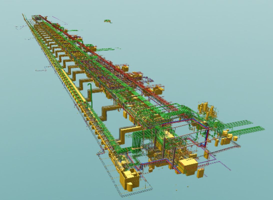
Image courtesy of Piero Valente, Group Leader Plant & Process at European Spallation Source ERIC
So how does ESS control all of this from a process point of view?
If you look at the picture below, you’ll see the actual engineering process (high level) together with the evolution of a space claim and refinement of design space, or rather the space allocation.
So how does ESS control all of this from a process point of view?
If you look at the picture below, you’ll see the actual engineering process (high level) together with the evolution of a space claim and refinement of design space, or rather the space allocation.
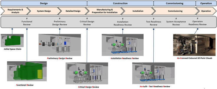
Image courtesy of ESS Spatial Integration
BUT WAIT!
Why does the process continue from as-designed into as-built and as-scanned??
Well, I never said that the EPL was purely design space configuration management. ESS has taken it a huge step forward to also incorporate, not only as built models, but rather As-Scanned models as well, which means there is a huge infrastructure in place to secure detailed 3D scans that can be imported into the EPL and put as an “overlay” to the design model like in the picture of the models below.
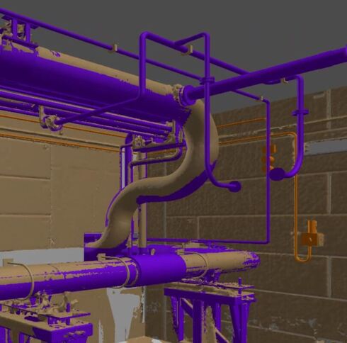
Image courtesy of ESS Spatial Integration Team
In such a model, inaccuracies between design model and actually installed becomes painfully apparent. I choose this image because I wanted to commend the extreme accuracy of this piping section, however there are numerous examples where errors have been caught which would have posed problems for other installation disciplines afterwards. Early correction of such mistakes is vital to avoid cascading effects for installation, and therefore scans are performed regularly and compared with the design model.
Below you can see an example of an As-Scanned Colored 3D Point Cloud only…. Remember the pipe from the previous picture….
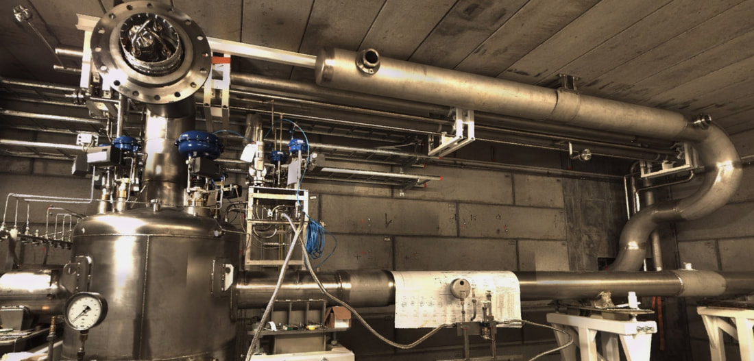
Image courtesy of ESS Spatial Integration Team
As we have now visually seen design requirements compared to actually installed, from a spatial integration perspective, I will show the same for tag requirements and installed physical assets in the next chapter. I know I promised this in the last chapter, but I could not resist showing it from a spatial integration perspective first.
It is my hope that this article can serve as inspiration for other companies as well as software vendors. I also want to express my gratitude to the European Spallation Source and to Peter Rådahl, Head of Engineering and Integration department in particular for allowing me to share this with you.
Bjorn Fidjeland
 RSS Feed
