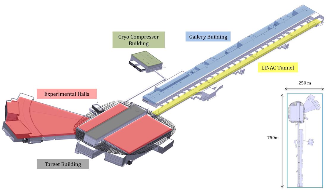
Image courtesy of European Spallation Source ERIC
In chapter four we will enter familiar and traditional PLM territory as we will take a closer look at product designs and EBOM’s (Engineering Bill Of Materials). European Spallation Source face the complexities of pure Engineer To Order (ETO) which means that they will only manufacture one of the designed products in the facility, as well as product designs that will be manufactured in series.
It is important to note that some of the products going into the facility was not even invented at the time the decision was made to build the European Spallation Source.
If you would like to read the previous chapters first before we take a deeper dive, you can find them here:
PLM tales from a true megaproject Ch. 1
PLM tales from a true megaproject Ch. 2 – Functional Breakdown Structure
PLM tales from a true megaproject Ch. 3 – Location Breakdown Structure
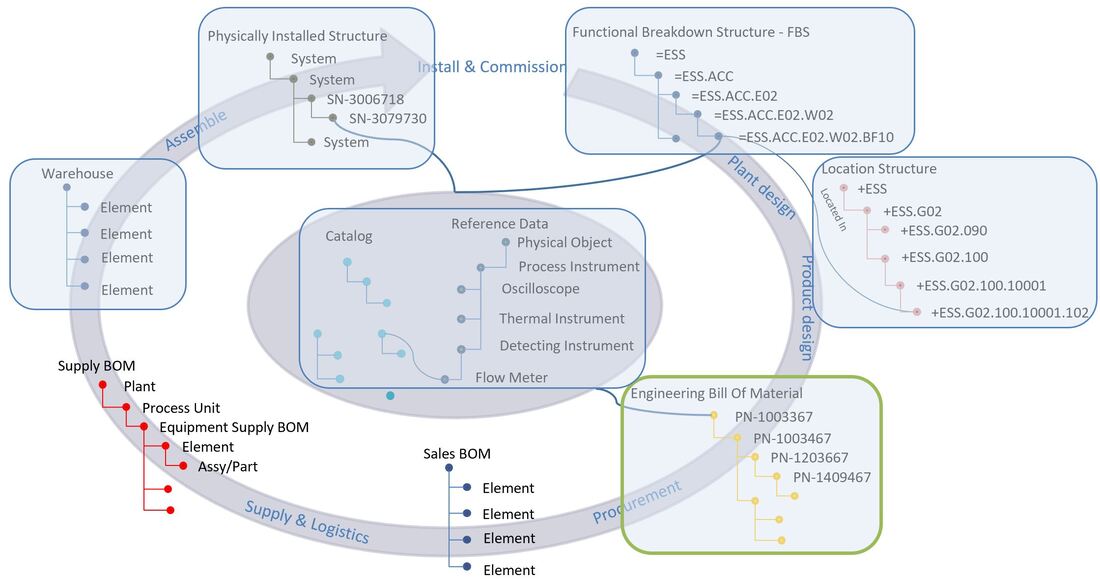
If you’d like to familiarize yourself more with the concepts of the different structures, please visit:
Plant Information Management - Information Structures
Figure 1.
As the management of product designs and their data is the home turf of any PLM system (Product Lifecycle Management), this area of the plant PLM platform has been left as much out of the box as possible, but I’ll go through some examples all the same.
The EBOM consists of Parts ordered in a hierarchical structure usually largely defined by mechanical product engineering and their design model. The structure is in itself multidiscipline, meaning that it contains mechanical parts, electrical parts and sometimes parts representing other things like drops of glue, software etc.
Based on an EBOM, one or many products can be manufactured. In other words, it is generic in nature.
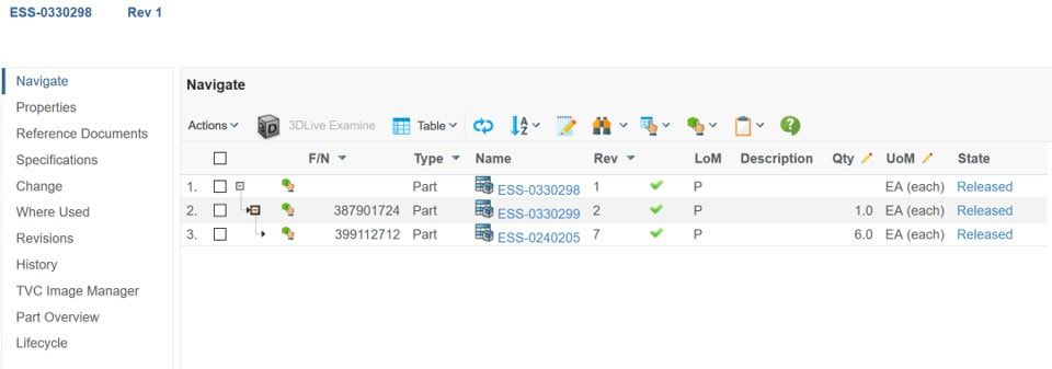
Figure 2. Image courtesy of European Spallation Source ERIC
The image above is from the plant PLM system and shows a simple EBOM which we can see is released. So what does released mean? Well It means that it is ready seen from the product engineering aspect. Such a released product design can be selected to fulfill one or many functional locations (tags) in the overall facility, as we discussed in chapter 1.
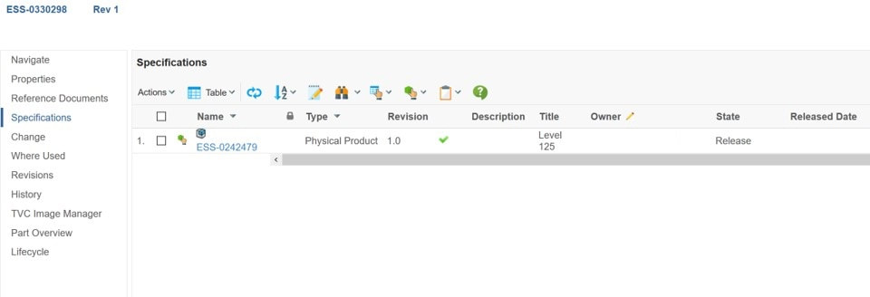
A part is specified by a specification, so it has specifying documentation connected in the form of a 3D model, a drawing or a document
Figure 3. Image courtesy of European Spallation Source ERIC
In our example in figure 3 there is a 3D model associated, which is specifying the mechanical aspects of the part (note: I have masked owner and released date).
In order to release a part and ultimately an EBOM consisting of parts, a few PLM principles must be observed. Specifying information must always be released prior to the release of the part. So bottom up.
The same is true for the EBOM. Child parts must be released before the parent part can be released. (this is the opposite of the release of the functional structure, but we’ll discuss that in a later chapter)
To govern the release process, a Change Order is used (in PLM also referred to as ECO or Engineering Change Order). In many serial manufacturing companies, it is common to have a process prior to deciding if a change should be implemented. This is because they want to make very sure that they understand all possible impacts a design change might have before they manufacture millions of their products based on the new design.
Such a process, in PLM often referred to as ECR or Engineering Change Request, is omitted at ESS, however the same analysis is performed early on in the change order process.
The release process is one of the areas where ESS have deviated from the out of the box solution in order to streamline as much as possible for their needs.
Let’s have a look at the process with another example.
Figure 4. Image courtesy of European Spallation Source ERIC
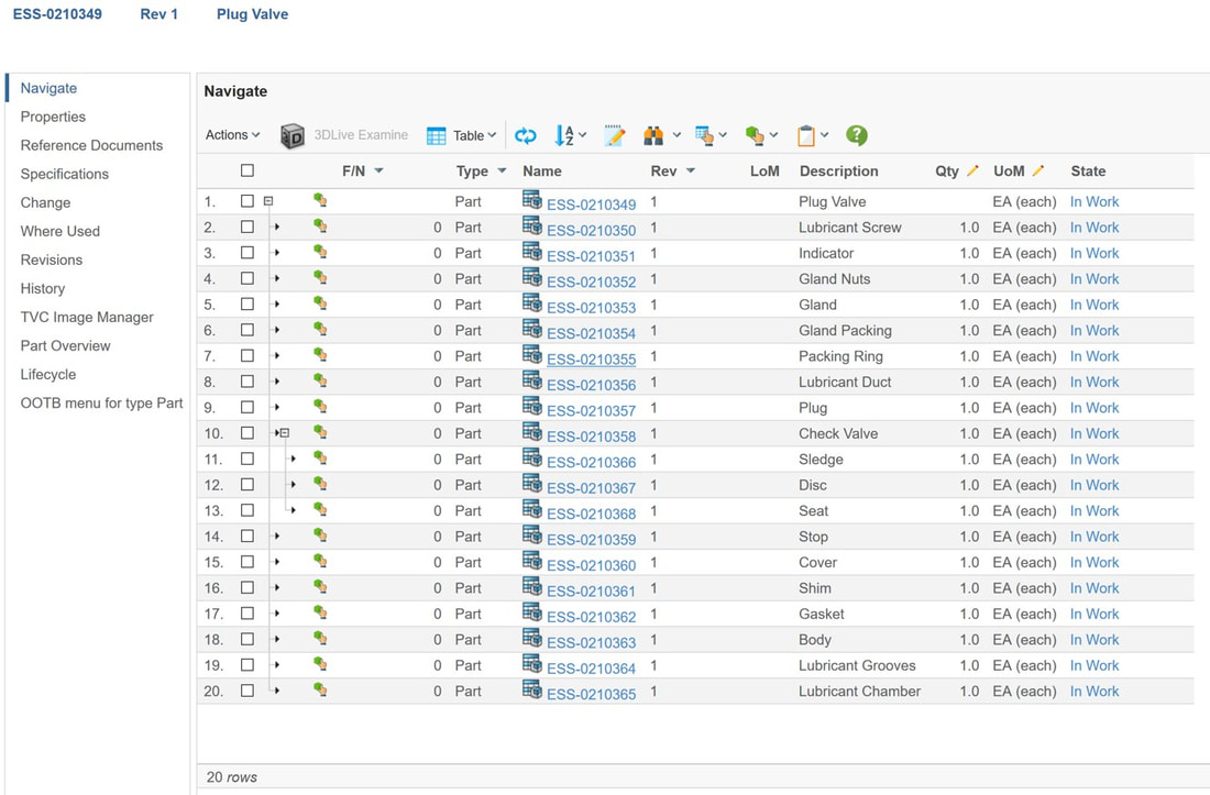
Figure 4 shows an EBOM structure used for training at ESS (It is not an ESS design, but merely an example I’ve created in their plant PLM system). Please observe that the EBOM of this plug valve contains a few parts, is three levels deep and is currently in a lifecycle state called In Work (there are more lifecycle states than showed in the images of this article). All Parts and specifications have individual lifecycle states.
Figure 4 shows an EBOM structure used for training at ESS (It is not an ESS design, but merely an example I’ve created in their plant PLM system). Please observe that the EBOM of this plug valve contains a few parts, is three levels deep and is currently in a lifecycle state called In Work (there are more lifecycle states than showed in the images of this article). All Parts and specifications have individual lifecycle states.
Figure 5. Image courtesy of European Spallation Source ERIC
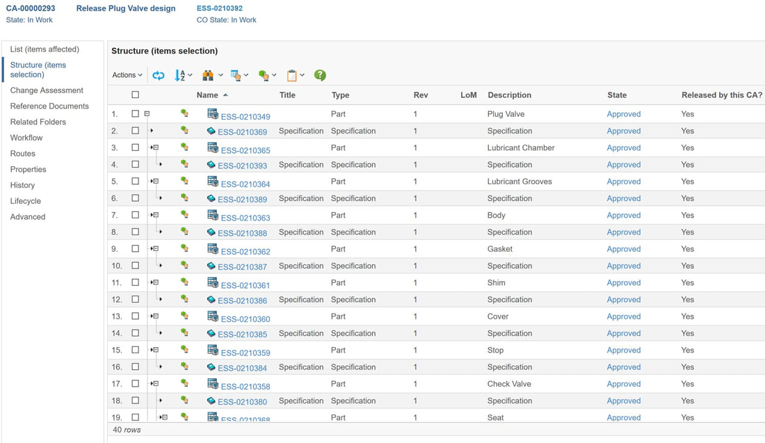
The image above is seen from the Change Order governing the move of both parts and specifications through their lifecycle states. We can see at the top left of the image that the CO (Change Order) is in “In Work” state. I’ve chosen to let one CO be responsible for the release of the full EBOM and all associated specifications, but I could have split the responsibility across multiple CO’s if I’d wanted to.
In figure 5 we can also see that all parts and their specifications are in state Approved. This means that the responsible engineering discipline feels that they are ready and have done their part of the work
Figure 6. Image courtesy of European Spallation Source ERIC
The last stretch of the release process is to move all the parts and their specifications from the Approved state to the Released state.
A workflow with electronic signatures is responsible for doing this. The workflow above states that Bjorn Fidjeland… (Yes, me) is responsible for reviewing the entire EBOM and all specifications. In a real live process, the members of a CDR (Critical Design Review) are listed as reviewers, and one or more final approvers assumes responsibility for the release. At ESS the CDR is a multi-discipline review with both internal and external stakeholders.
Normally it is not allowed to have the same person as both reviewer and approver, but since I’ve got admin rights to this environment, and did not want to show the names of ESS reviewers and approvers, the example is as it is.
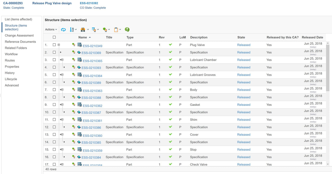
When the last person in the workflow sequence has approved, all specifications and parts governed by the Change Order are automatically promoted from Approved state to Released state, and the Change Order itself is marked complete. The system itself takes care of the bottom up release rules of the EBOM.
Figure 7. Image courtesy of European Spallation Source ERIC
Figure 7 shows the fully released EBOM, including all specifications governed by this one Change Order.
The next chapter will be about how ESS manages information about their physical assets, how physically installed assets are linked to the facility’s tag requirements in the Functional Breakdown Structure, where they are located in the Location Breakdown Structure and from what product design they originate from.
It is my hope that this article can serve as inspiration for other companies as well as software vendors.
I also want to express my gratitude to the European Spallation Source and to Peter Rådahl, Head of Engineering and Integration department in particular for allowing me to share this with you.
Bjorn Fidjeland


 RSS Feed
