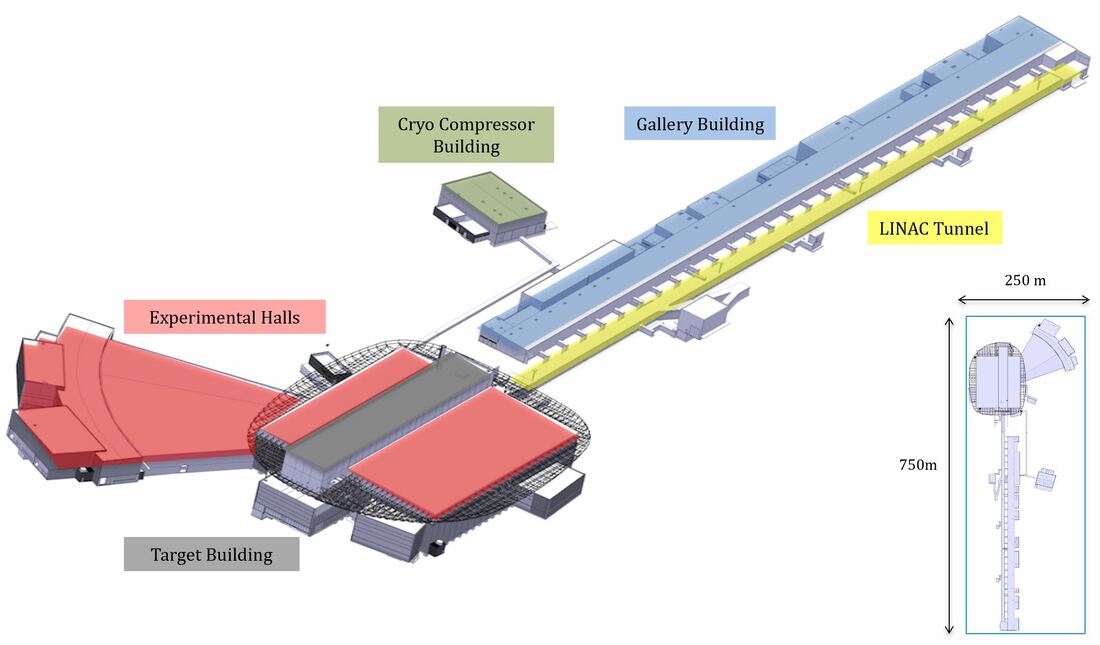
Image courtesy of Fabien Rey, Group Leader Machine Engineering Service Group at European Spallation Source ERIC
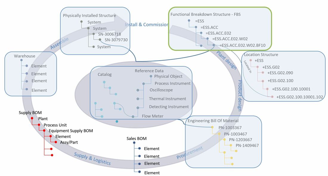
In this chapter we are going to take a look at how the functional breakdown structure is implemented at the European Spallation Source. The functional structure is a functional decomposition of systems and subsystems all the way down to individual functions, or as ESS calls them, components. The Functional Breakdown Structure contains a consolidated view of data from all plant engineering disciplines including electrical, plant & process and mechanical.
If you would like to read chapter one first before we take a deeper dive, you can find it here:
PLM tales from a true megaproject Ch. 1
If you’d like to familiarize yourself more with the concepts of the different structures, please visit:
Plant Information Management - Information Structures and
Plant Engineering meets Product Engineering in capital projects
Figure 1.
The first thing you’ll notice is the tagging. It was decided to use the standard EN/ISO 81346 as a common master tag at the European Spallation Source. The equal sign means that it is the functional aspect, however anybody familiar with the standard will notice something a bit odd. The first 2 levels are not quite according to standard. It was decided that the first level was to be ESS, and the second levels ACC (Accelerator), TS (Target Station), NSS (Neutron Scattering Systems) and INFR (Infrastructure). Anything below the first and second level is according to the guidelines of the standard.
The first thing you’ll notice is the tagging. It was decided to use the standard EN/ISO 81346 as a common master tag at the European Spallation Source. The equal sign means that it is the functional aspect, however anybody familiar with the standard will notice something a bit odd. The first 2 levels are not quite according to standard. It was decided that the first level was to be ESS, and the second levels ACC (Accelerator), TS (Target Station), NSS (Neutron Scattering Systems) and INFR (Infrastructure). Anything below the first and second level is according to the guidelines of the standard.
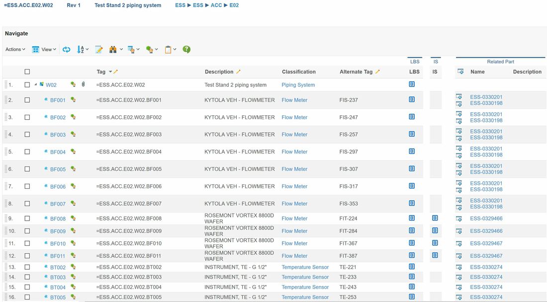
Figure 2. Image courtesy of European Spallation Source ERIC
The image above is from the plant PLM system and shows the functional breakdown structure of the Test Stand 2 piping system as an example. At the time of writing, the functional breakdown structure contains about 50.000 tags, but is expected to grow to well over 1 million tags.
Let’s go through what we see in the image, and use the first row – W02 (the Test Stand 2 piping system) as an example in the beginning.
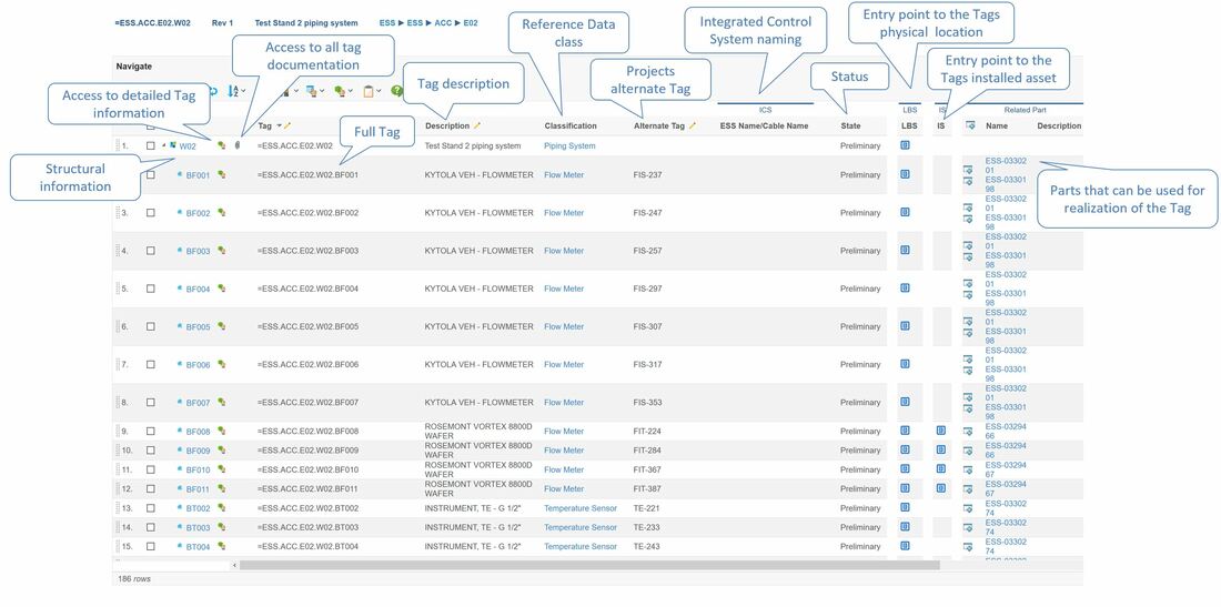
Figure 3. Image courtesy of European Spallation Source ERIC
The first column shows the tag name of the individual functional object (W02). The second column with the little green icon gives you the option to zoom in on the object if further details are needed, for instance all the attribute values of the object coming from object type or class (European Spallation Source uses ISO 15926-4 as a basis for their master reference data).
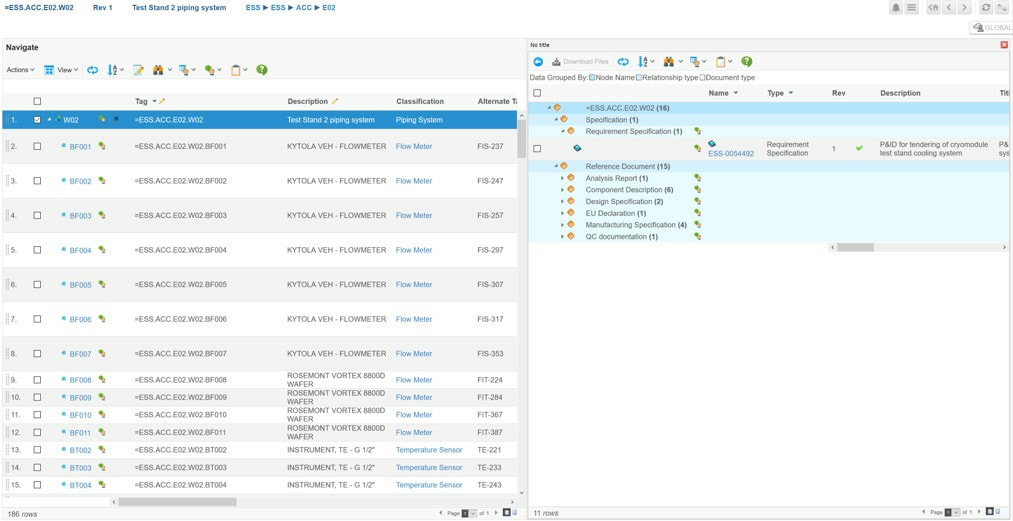
The third column shows a paperclip if there are specifying documentation associated with the tag. In figure 4 we can see that the Test Stand 2 piping system has one released P&ID (the green check mark means that it has the lifecycle state released), and that there are 15 other reference documents associated.
Figure 4. Image courtesy of European Spallation Source ERIC
The Tag column shows the full functional master tag, and the description column indicates a description of the functional object.
The classification column shows what kind of functional object it is. This refers to the master reference data class that is used to describe the properties or attributes this specific tag has got. In order to explain better we need to take a step back.
I mentioned that the European Spallation Source opted to use ISO 15926-4 as a basis for their master reference data. This means that there is a vast library of classes that defines what attributes, let’s say a Temperature Sensor should have, and also what letter codes (defined based on EN 81346) it should have. So, when a functional object is first created, it only has basic attributes that are shared across all functional objects, however when the system is told that it is a Temperature Sensor, it gets all the attributes defined for the class Temperature Sensor in addition to it’s tag which is computed by the parent object’s tag, the letter code and the number of other Temperature Sensors at this level in the functional breakdown structure plus one.
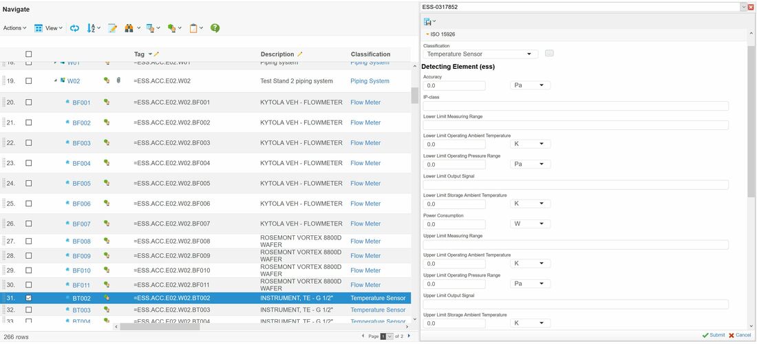
Figure 5. Image courtesy of European Spallation Source ERIC
The image above shows some of the attributes for the selected Temperature Sensor tag, but without operational data.
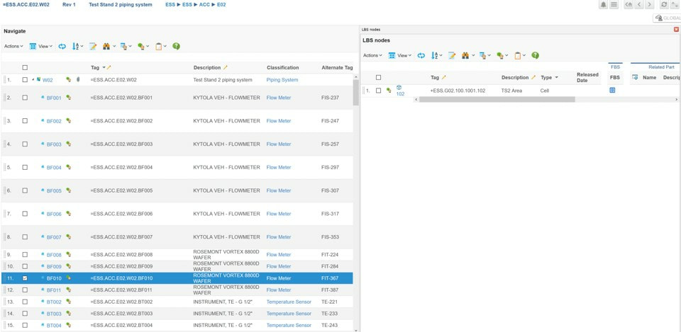
The LBS (Location Breakdown Structure) column in figure 3 allows you to see at what physical location the functional object is located.
If the functional object is a pipe or cable that spans multiple locations, then several physical locations are displayed in the split view as shown in figure 6.
Figure 6. Image courtesy of European Spallation Source ERIC
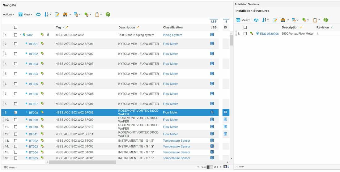
The IS column in figure 3 refers to the actually installed asset in the plant that implements the functional object requirements (physical item with serial number). See figure 7.
The IS column in figure 3 refers to the actually installed asset in the plant that implements the functional object requirements (physical item with serial number). See figure 7.
Figure 7. Image courtesy of European Spallation Source ERIC
The released part column in figure 2 gives an overview of what released product designs (Engineering Bill Of Materials) or standard parts that can fulfill the functional object requirements (there might be several options prior to procurement, however the installed asset will only have an association to one part as it was manufactured based on that particular product design).
So from one view in the plant PLM system, the European Spallation Source is able to access all related data to all functional objects in their functional breakdown structure from design and engineering through installation, commissioning, operations, maintenance and ultimately decommissioning.
The next chapter will be about the Location Breakdown Structure.
It is my hope that this article can serve as inspiration for other companies as well as software vendors. I also want to express my gratitude to the European Spallation Source and to Peter Rådahl, Head of Engineering and Integration department in particular for allowing me to share this with you.
Bjorn Fidjeland

 RSS Feed
