Image courtesy of European Spallation Source ERIC
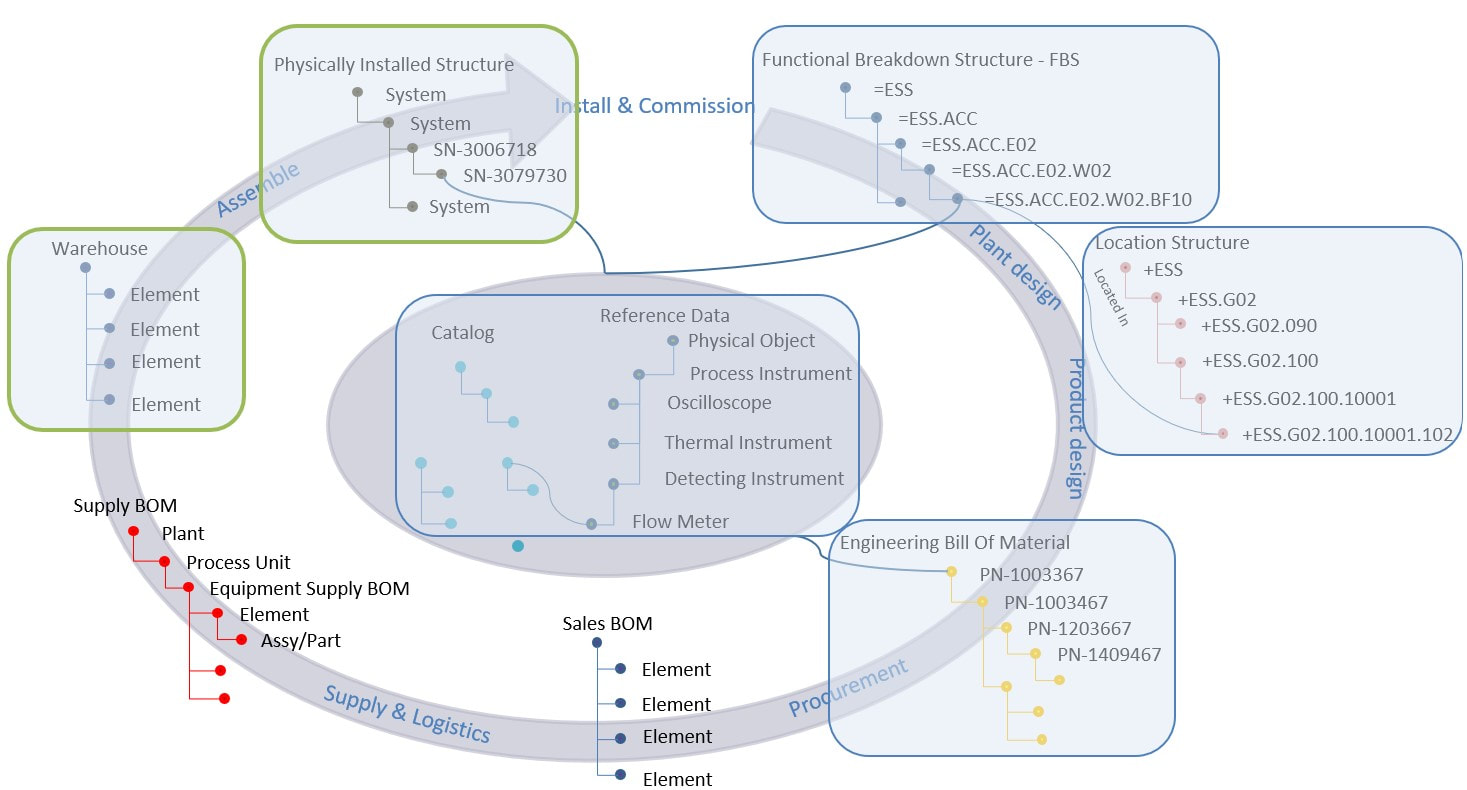
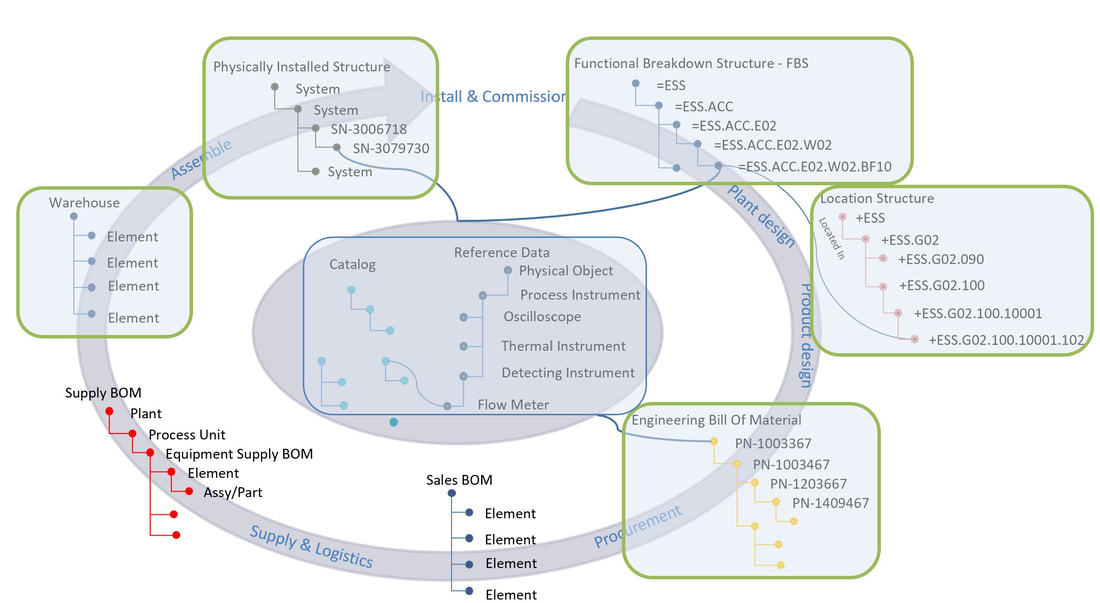
In this chapter we’re going to take a look at how physically installed assets are treated from an information management perspective, how assets are related to their specifying tag information, physical location and work performed on the assets themselves from arrival on site to installation and commissioning.
If you would like to read previous chapters first before we take a deeper dive, you can find them all here: Archive
Figure 1.
As physical assets arrive at ESS they are registered in the Enterprise Asset Management (EAM) system through a goods receival process, and work orders are then required to install the asset to fulfill the tag requirements stated in the Functional Breakdown structure during design and engineering.
As physical assets arrive at ESS they are registered in the Enterprise Asset Management (EAM) system through a goods receival process, and work orders are then required to install the asset to fulfill the tag requirements stated in the Functional Breakdown structure during design and engineering.
Figure 2. Image courtesy of European Spallation Source ERIC
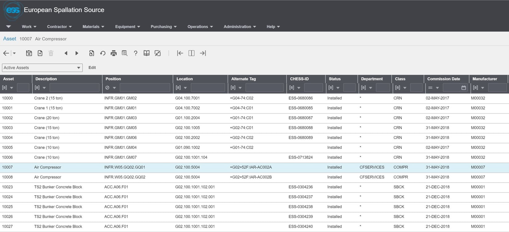
Figure 2 is from the Enterprise Asset Management system and shows a subset of installed assets. Note that the tags they fulfil are called Positions. Information regarding tag/position, location etc. comes from the plant PLM system via integration whereas the asset information is registered in the EAM system and managed there. All asset documentation is then fed back to the plant PLM system for consolidation across all information structures.
Figure 2 is from the Enterprise Asset Management system and shows a subset of installed assets. Note that the tags they fulfil are called Positions. Information regarding tag/position, location etc. comes from the plant PLM system via integration whereas the asset information is registered in the EAM system and managed there. All asset documentation is then fed back to the plant PLM system for consolidation across all information structures.
Figure 3. Image courtesy of European Spallation Source ERIC
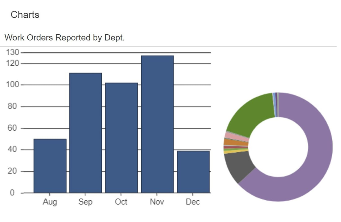
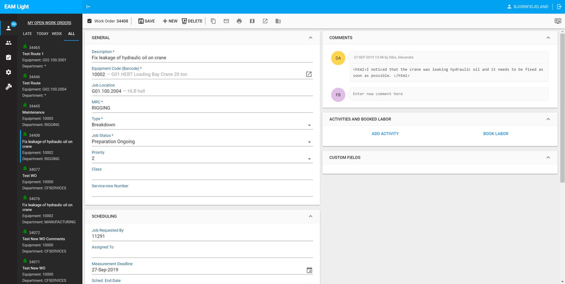
The EAM system governs work performed on assets in the facility from preparation and rigging to installation work orders, commissioning and maintenance work orders. Figure 3 shows a chart of different types of work orders executed over a short period of time.
The information from the plant PLM system entered during design and engineering is now put to good use as it provides all information about what function the asset is supposed to fulfil in the facility, how it should be calibrated and where it is to be installed. All this information is accessible directly from the EAM system for the people performing the work.
Figure 4. Image courtesy of European Spallation Source ERIC
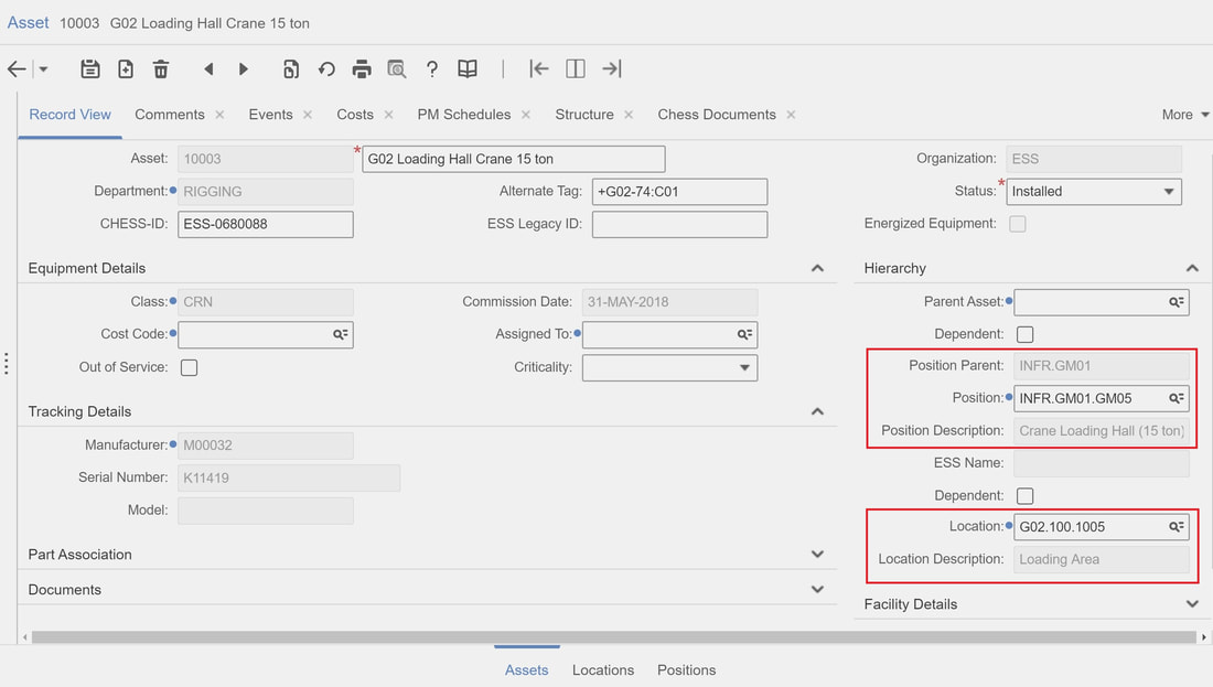
Figure 4 shows detailed information about the asset. Through the Position/Tag and Location, all information and documentation from engineering is available. Furthermore, we can see that the asset is installed and that commissioning has been performed.
All documentation including needed certification regarding the Asset, together with design documentation is available through one screen for maintenance personnel. To make access and input of relevant information easier for persons working in the field, a simple user interface for rugged hand held devices has been put in place as an overlay to the EAM system.
Figure 5. Image courtesy of European Spallation Source ERIC
So with this, the “information circle” is complete with structured data all the way from design and engineering through installation, commissioning, operations and maintenance.
So with this, the “information circle” is complete with structured data all the way from design and engineering through installation, commissioning, operations and maintenance.
Figure 6. Image courtesy of European Spallation Source ERIC
Using this principle has allowed the European Spallation Source to move from document centric handovers between lifecycle phases to data centric transitions where the handover is in terms of responsibility for the data needed.
But hold on a second. This all explains the different data structures needed throughout the plant lifecycle. However, it does not explain how data on the different entities across the structures can be interpreted and compared to gain meaning and insight. So, how to achieve interoperability of data across disciplines and software tools?
That will be the topic of my next article in this series.
It is my hope that this article can serve as inspiration for other companies as well as software vendors. I also want to express my gratitude to the European Spallation Source and to Peter Rådahl, Head of Engineering and Integration department in particular for allowing me to share this with you.
Bjorn Fidjeland


 RSS Feed
