Follow us at
plmPartner
  • Home
  • About
  • Blog
  • Archive
  • Contact
  • Video Log
  • Learning Center
  • Privacy Policy

PLM Benchmark 3 – EPC 2  What did they do and why?

8/2/2018

1 Comment

 
Picture
This is an article in the series regarding PLM benchmarking among operators, EPC’s and product companies.
The articles cover the motivation for doing as they did, and where their main focus was put in order to achieve their goals.

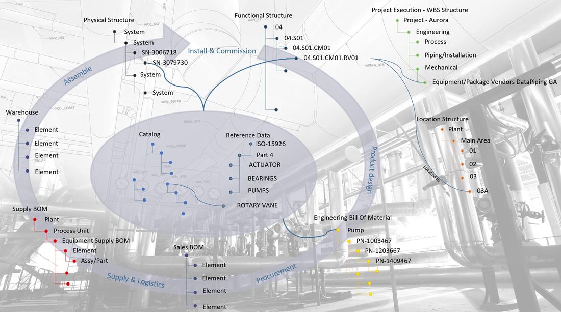
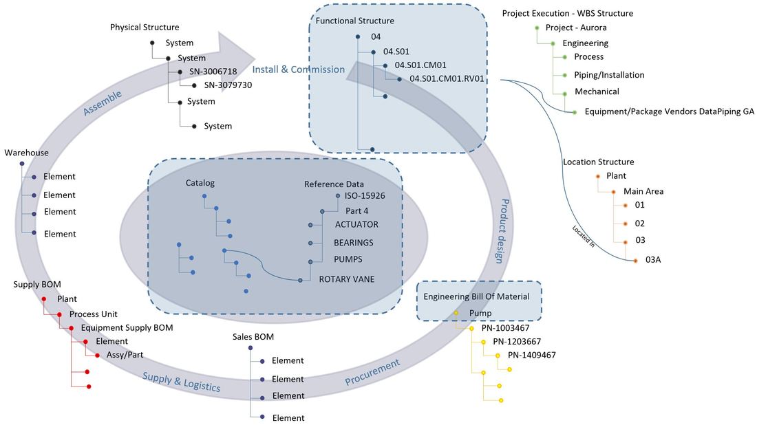
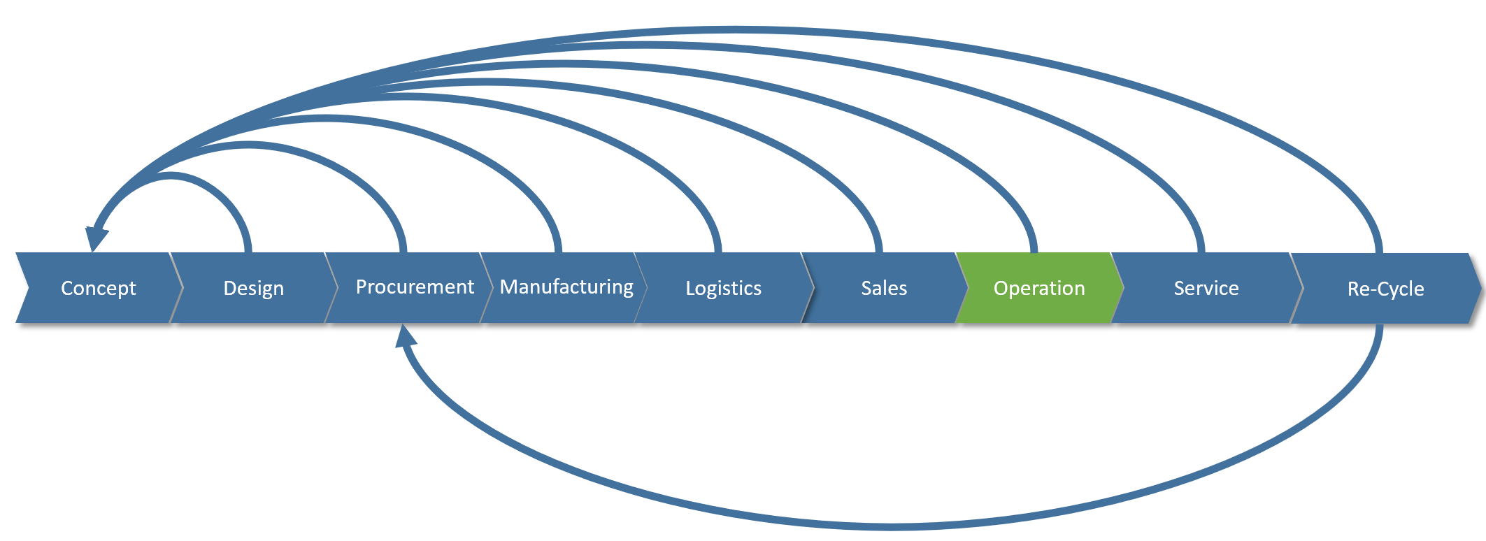
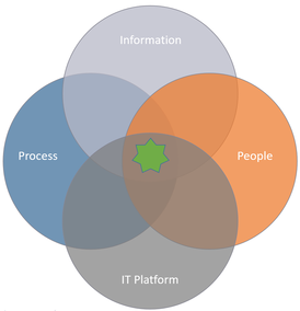
I will continue to use my information structure map, or the “circle of life” as a client jokingly called it, to explain where the different companies put their focus in terms of information management and why.
Picture
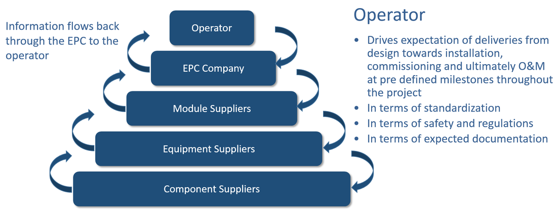
​EPC 2 had a slightly different focus from the EPC in my previous article as they were in an industry where there is a less clear split between Engineering Procurement and Construction companies and Product companies in the capital project value chain.
This company had the challenges of both EPC’s and product companies in ETO (Engineer To Order) projects as they owned several product companies, and naturally used a lot of their products in their EPC projects.
​
Picture
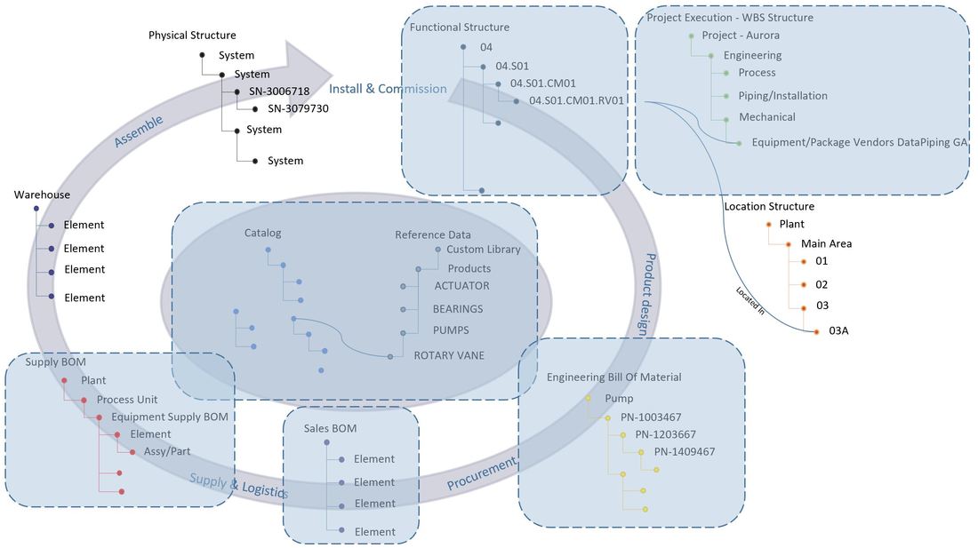
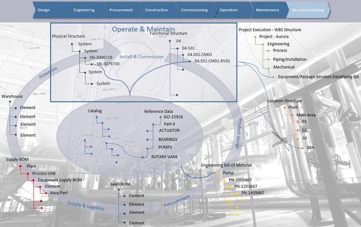
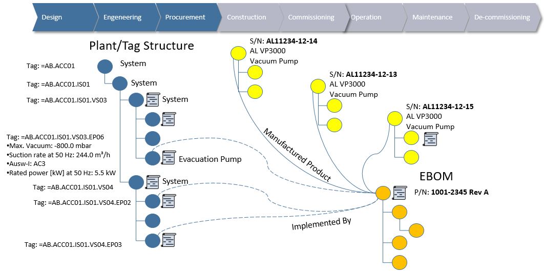
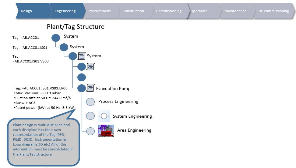
Figure 2 shows the different data structures that EPC 2 focused on

Their first objective was to respond to fearsome competition from other parts of the world who suddenly emerged on the global scene. In order to do so it was considered crucial to limit the amount of engineering hours used to gain projects. To achieve this, they decided to build a catalog of re-usable data structures with different perspectives (plant, product, execution) in order to promote a controlled re-use of both plant and product engineering data. Similarly, as for EPC 1 they recognized that standardization across disciplines would be necessary to make it all work. The reference/master data put in place for all disciplines to share was a proprietary company standard.

Secondly, they needed to replace a homegrown engineering data hub. This homegrown solution was very impressive indeed and contained a lot of functionality that commercial systems lack even today, however its architecture was built around processes that did no longer work as EPC 2 entered new markets.

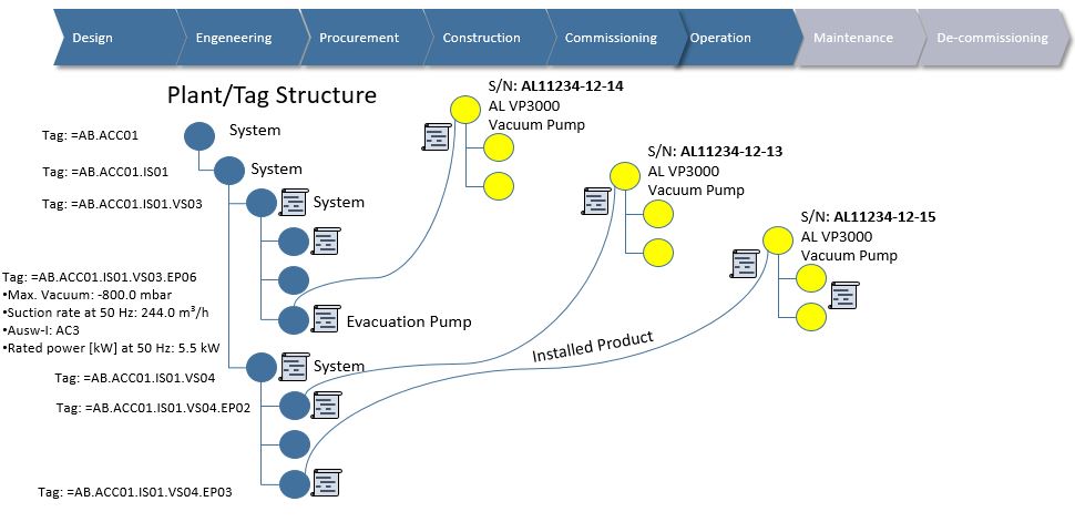
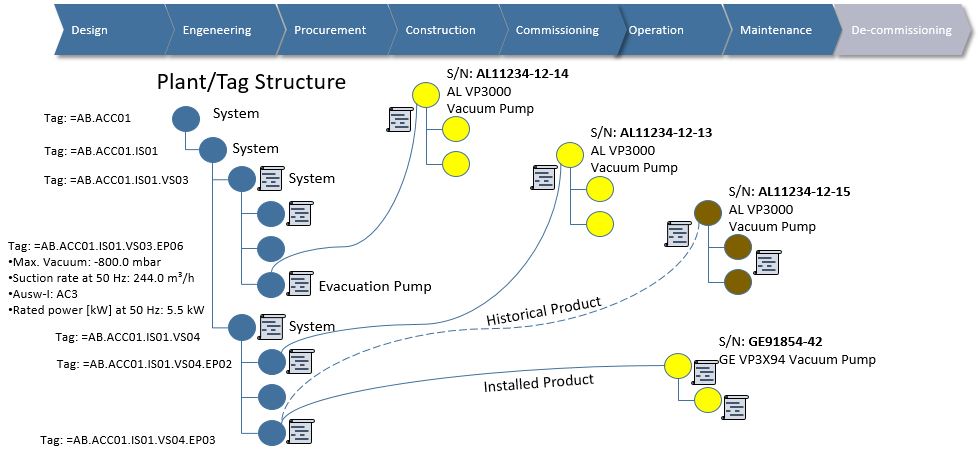
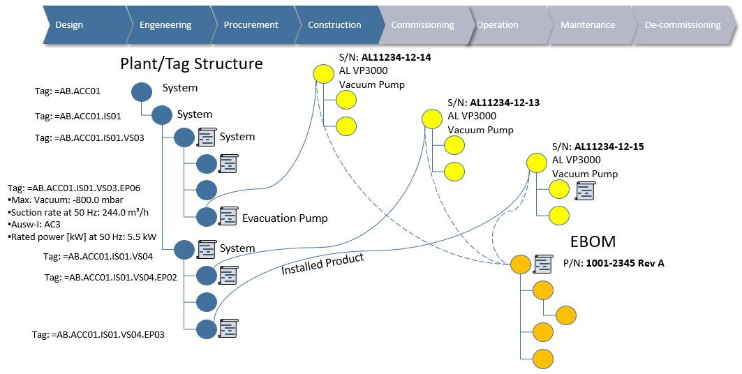
Thirdly they wanted to connect their plant engineering disciplines with the various product engineering disciplines throughout their own product companies worldwide. Naturally this meant run-time sharing and consolidation of data on a large scale. The emergence of the catalog with different aspects meant that plant engineering could pick systems and products from the catalog and have auto generated project specific tag information in the functional structure of their projects. It also meant that product engineering would be able to either generate a unique Engineer To Order bill of material if needed, or if plant engineering had not done any major modifications, link it to an already existing Engineering Bill of Material for the full product definition. 
​
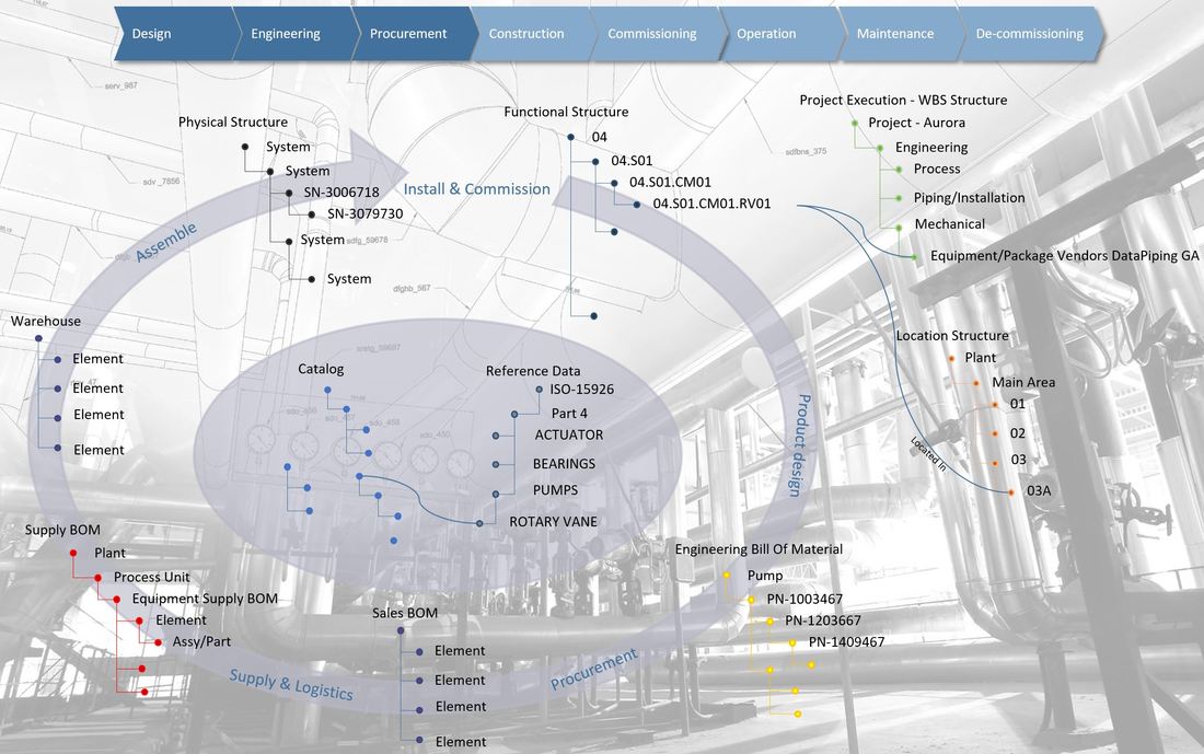
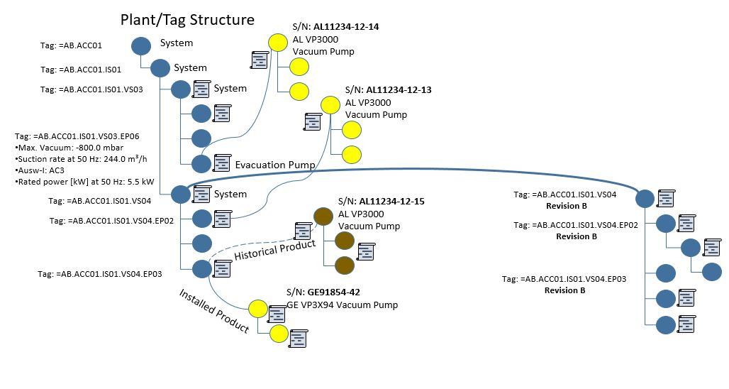
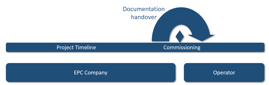
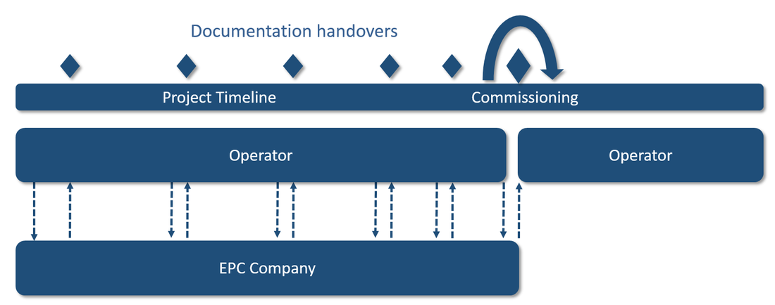
Their fourth objective was to obtain full traceability of changes across both plant and product engineering disciplines from FEED (Front End Engineering & Design) to delivered project. The reason for this objective was twofold. One part was to be able to prove to clients (operators) where changes originated from (largely from the client itself), and secondly to be able to measure what changes originated from their own engineering disciplines without project planning and execution knowing about it….. Does it sound familiar?
In order to achieve this, engineering data change management was enforced on both FEED functional design structures (yes, there could be several different design options for a project) and the functional structure in the actually executed EPC project. The agreed FEED functional structure was even locked and copied to serve as the starting point for the EPC project. At this point all data in the functional structure was released, subjected to full change management (meaning traceable Change Orders would be needed to change it) and made available to project planning and execution via integration.
Picture
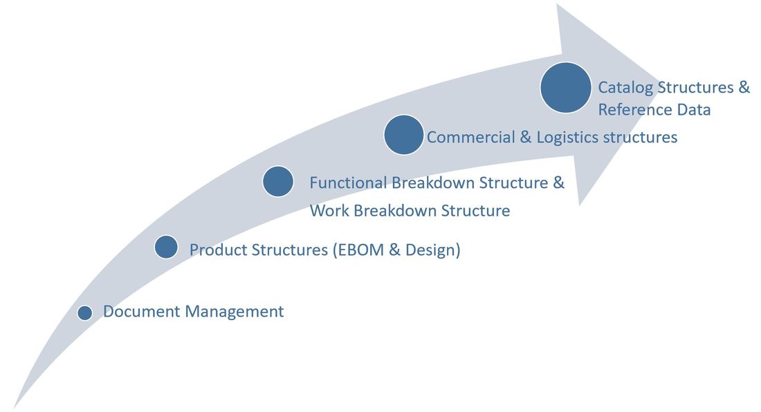
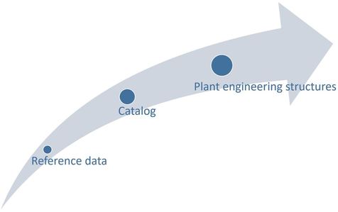
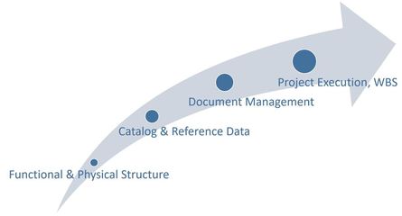
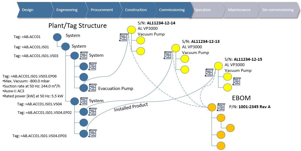
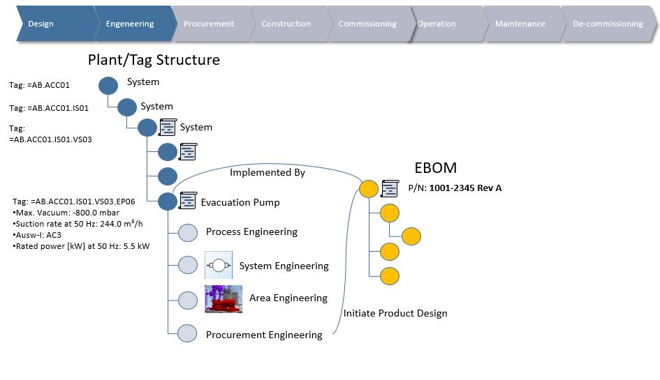
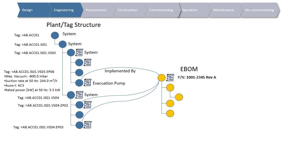
Figure 3 shows the sequence of data structures that was focused on in the implementation project.

Since product design and delivery was a large portion of their projects, the Engineering Bill of Material (EBOM) and variant management (the catalog structures) got a lot more focus compared with EPC 1 in my previous article. This was natural because, as mentioned, EPC 2 owned product companies and wanted to make a shift from Engineer To Order (ETO) towards more Configure To Order (CTO).
It was however decided to defer the catalog structures towards the end because they wanted to gain experience across the other aspects as well before starting to create the catalog itself.


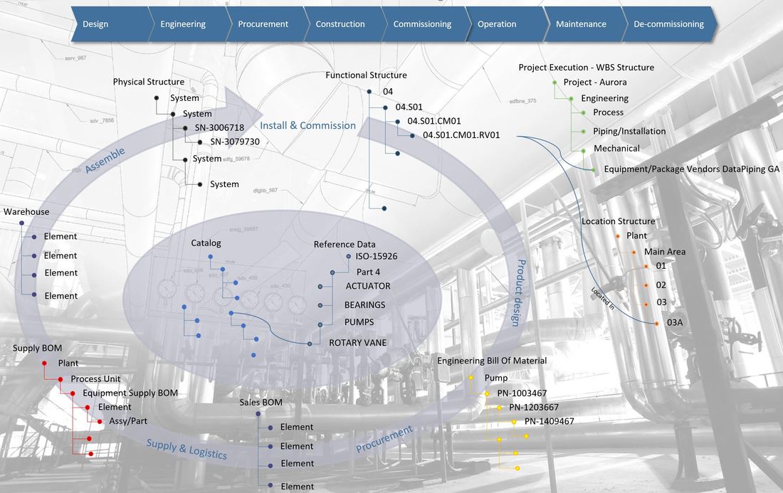
The Functional Structure with the consolidated plant design, project specific data and associated documentation was out next together with the establishment of structures for project execution (WBS), estimation and control (Sales structure), and logistics (Supply structure).

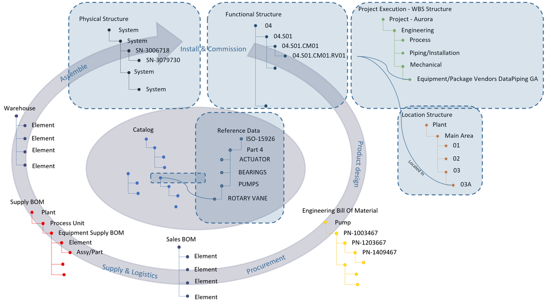
Once the various data structures were in place, the focus was turned to “gluing it all together” with the re-usable catalog structures and the reference data which enabled interoperability across disciplines.

A more comprehensive overview explaining the different structures can be found in the article:
Plant Information Management - Information Structures, and further details regarding each information structure are discussed in:
Plant Engineering meets Product Engineering in capital projects
Handover to logistics and supply chain in capital projects
Plant Information Management - Installation and Commissioning
Plant Information Management – Operations and Maintenance

​Bjorn Fidjeland


The header image used in this post is by 8vfand and purchased at dreamstime.com
1 Comment

PLM Benchmark 2 – EPC 1 What did they do and why?

4/27/2018

0 Comments

 
Picture
This is the second article in the series regarding PLM benchmarking among operators, EPC’s and product companies where I share some experiences with you originating from different companies.
The articles cover the motivation for doing as they did, and where their main focus was put in order to achieve their goals.
In this series I use my information structure map, or the “circle of life” as a client jokingly called it, to explain where the different companies put their focus in terms of information management and why. 
Picture
​EPC 1’s first objective was to replace an in-house built engineering data hub. The reason for this was that over the years, needs and requirements had changed both from customers (operators) as the EPC went global, and internally within the organization. This situation lead to more and more customizations of the engineering data hub resulting in sky rocketing cost of ownership, and ironically, less and less flexibility.

This is by no means a unique situation as many EPC’s were forced to build such hubs in the late nineties for consolidation and control of multidiscipline plant information since no software vendor at the time could support their needs.

Secondly it was considered crucial to enable standardization and re-use of previously delivered designs and engineering data.
A huge effort was put on building reference data for sharing and alignment across plant engineering disciplines, procurement and ultimately client handover of Documentation For Installation & Operations (DFI/DFO). An ISO 15926 ontology was put in place for this purpose.
The main reason for enabling standardization and re-use of engineering data however, was to reduce the gigantic number of engineering hours that were spent in the early phases of each project delivery. Especially during the FEED phase (Front End Engineering and Design). Another important reason was to connect engineering with procurement and the wider supply chain more seamlessly.
Picture
​Figure 2. shows what information structures EPC 1 put most emphasis on. Quite naturally the Functional Location structure (tag structure, multi discipline plant design requirements) received a lot of focus. To enable re-use and efficient transfer of data, both the reference data and a library of re-usable design structures using the reference data was built.

Extensive analysis of previously executed projects revealed that even if the EPC had a lot of engineering concepts and data that could be re-used across projects, they more often than not created everything from scratch in the next project. In order to capitalize on and manage the collective know-how of the organization, the re-usable design structures received a lot of focus.

EPC 1 also faced different requirements from operators with respect to use of tagging standards depending on what parts of the world they delivered projects to, so as a consequence, multiple tagging standards needed to be supported. It was decided that no matter what format the operator wanted to receive, all tags in all projects would be governed by an internal “master-tag” in the EPC’s own system while communicated to the customer in their specified format.

The third focus area was an extensive part (or article) library with internal part numbers and characteristics showing what kind of products could fulfill the tag requirements in the functional structure. Each part was then linked via a relationship to objects representing preferred suppliers of that product in different regions of the world. This concept greatly aided engineering procurement when performing Material Take-Off (MTO) since each tag would be linked to a part where preferred supplier could be selected. 
Picture
​EPC 1 chose to focus on the reference data first in order to get a common agreement regarding needed data across their disciplines during the EPC project lifecycle. Next in line was the catalog of re-usable engineering structures. These structures could be used and selected as a starting point in any EPC project.
The third delivery in the project centered around delivering the capabilities to create and use the different plant engineering structures (functional structure, tags, with connected parts where both entities used the same reference data )
 
An overview explaining the different structures can be found in the article:
Plant Information Management - Information Structures, and further details regarding each information structure are discussed in:
Plant Engineering meets Product Engineering in capital projects
Handover to logistics and supply chain in capital projects
Plant Information Management - Installation and Commissioning
Plant Information Management – Operations and Maintenance

Bjorn Fidjeland

The header image used in this post is by Viacheslav Iacobchuk and purchased at dreamstime.com
0 Comments

PLM Benchmark – Operator 1 What did they do and why?

3/9/2018

0 Comments

 
Picture
This as a first in a series of articles where I share some experiences with you from different product companies, EPC’s and operators.
The articles will cover the motivation for doing as they did, and where their main focus was put in order to achieve their goals.

There is a span in the different experiences of almost 20 years… I would like you to reflect a bit on that and keep in mind some of the buzzwords of today. Especially digital twin, IOT and Big Data analytics.
In this series I will use my information structure map, or the “circle of life” as a client jokingly called it, to explain where the different companies put their focus in terms of information management strategy and why.

An overview explaining the different structures can be found in the article:
Plant Information Management - Information Structures, and further details regarding each information structure are discussed in:
Plant Engineering meets Product Engineering in capital projects
Handover to logistics and supply chain in capital projects
Plant Information Management - Installation and Commissioning
Plant Information Management – Operations and Maintenance
​
Picture
Operator 1’s first objectives was to shorten the project execution time from design through installation and commissioning by letting the projects information model be gradually built up through all project phases and by all stakeholders in one common platform.
By doing it this way there would be no handover of documentation but rather a handover of access and responsibility of data. A large focus was put on standardizing information exchange between both stakeholders in the capital projects and between computer systems. The entry point to all information was a 3D representation of the data structures!

Makes you think of digital twin……. However this initiative was before anybody had heard of it...The 3D representation was NOT a design model, but rather a three-dimensional representation of the asset linked to all the information structures creating different dimensions or information layers if you will.

So it had to be quite small assets this operator was dealing with you might think?

Actually no, one of the assets managed was about a million tags. Concepts from the gaming industry like Level Of Detail and back-face culling were used to achieve the level of performance needed from the 3D side.
So why this enormous effort by an operator to streamline just the initial stages of an assets lifecycle?
I mean the operators real benefit comes from operating the asset in order to produce whatever it needs to produce, right?
​
Because it was seen as a prerequisite to capitalize on plant information in training, simulation, operations, maintenance and decommissioning. Two words summarizes the motivation: Maximum up-time. How to achieve it: operational run-time data from sensors linked and compared with accurate and parametric as-designed, as-built and as-maintained data.

​
Picture
​Figure 2. shows what information structures the operator put most emphasis on. Quite naturally the Functional structure (tag structure and design requirements), and corresponding physically installed asset information was highly important, and this is what they started with (see figure 3). Reference Data to be able to compare and consolidate data from the different structures was next in line together with an extensive parts (article) catalog of what could be supplied by whom in different regions of the world.
Picture
There was an understanding that a highly document-oriented industry could not shift completely to structured data and information structures overnight for everything, so document management was also included as what was regarded as an intermediate step. The last type of structure they focused on was project execution structures (Work Breakdown Structures). This was not because it was regarded as less important, actually it was regarded as highly important since it introduced the time dimension with traceability and control of who should do what, or did what when. The reasoning behind it was that since work breakdown structures tied into absolutely everything, they wanted to test and roll out the “base model” of data structures in the three-dimensional world (the 3D database) before introducing the fourth dimension.

​Bjorn Fidjeland

​
The header image used in this post is by Jacek Jędrzejowski and purchased at dreamstime.com
0 Comments

Big Data and PLM, what’s the connection?

1/3/2018

3 Comments

 
Picture
I was challenged the other day to explain the connection between Big Data and PLM by a former colleague. The connection might not be immediately apparent if your viewpoint is from traditional Product Lifecycle Management systems which primarily has to do with managing the design and engineering data of a product or plant/facility.

However, if we first take a look at a definition of Product Lifecycle Management from Wikipedia:

“In industry, product lifecycle management (PLM) is the process of managing the entire lifecycle of a product from inception, through engineering design and manufacture, to service and disposal of manufactured products. PLM integrates people, data, processes and business systems and provides a product information backbone for companies and their extended enterprise.”
​
Traditionally it has looked much like this
Picture
Then let’s look at a definition of Big Data
​

“Big data is data sets that are so voluminous and complex that traditional data processing application software are inadequate to deal with them. Big data challenges include capturing data, data storage, data analysis, search, sharing, transfer, visualization, querying, updating and information privacy. There are three dimensions to big data known as Volume, Variety and Velocity.
Lately, the term "big data" tends to refer to the use of predictive analytics, user behavior analytics, or certain other advanced data analytics methods that extract value from data, and seldom to a particular size of data set. "There is little doubt that the quantities of data now available are indeed large, but that’s not the most relevant characteristic of this new data ecosystem." Analysis of data sets can find new correlations to "spot business trends, prevent diseases, combat crime and so on.”

Included in Big Data you’ll find data sets harvested from sensors within all sorts of equipment and products as well as data fed back from software running within products. One can say that a portion of Big Data is the resulting feedback from the Internet of Things. Data in itself is not of any value whatsoever, but if the data can be analyzed to reveal meaning, trends or knowledge about how a product is used by different customer segments then it has tremendous value to product manufacturers.
If we take a look at the operational phase of a product, and by that, I mean everything that happens from manufactured product to disposal, then any manufacturer would like to get their hands on such data, either to improve the product itself or sell services associated with it. Such services could be anything from utilizing the product as a platform for an ecosystem of connected products to new business models where the product itself is not the key but rather the service it provides. You might sell guaranteed uptime or availability provided that the customer also buys into your service program for instance.

 
The resulting analysis of the data should in my view be managed by, or at least serve as input to the product definition because the knowledge gleamed from all the analytics of Big Data sets ultimately impacts the product definition itself since it should lead to revised product designs that fulfills the customer needs better. It might also lead to the revelation that it would be better to split a product in two different designs going after two distinct end user behavior categories found as a result of data analysis from the operational phase of the products.
​
Connected products, Big Data and analysis will to a far greater extent than before allow us to do the following instead:
Picture
It will mean that experience throughout the full lifecycle can be made available to develop better products, tailor to new end user behavior trends and create new business models.

Note: the image above focuses on the feedback loops to product engineering, but such feedback loops should also be made available from for instance service and operation to manufacturing.

Most companies I work with tell me that the feedback loops described in the image above is either too poor, or virtually nonexistent. Furthermore, they all say that such feedback loops are becoming vital for their survival as more and more of their revenue comes from services after a product sale and not from the product sale itself. This means that it is imperative for them to have as much reliable and analyzed data as possible about their products performance in the field, how their customers are actually using them and how they are maintained.

For these companies at least, the connection between Big Data analysis and its impact on Product Lifecycle Management is becoming clearer and clearer.


Bjorn Fidjeland


The header image used in this post is by garrykillian and purchased at dreamstime.com

3 Comments

Plant Information Management – Operations and Maintenance

1/29/2017

0 Comments

 
Picture
This post is a continuation of the posts in the Plant Information Management series of:
“Plant Information Management - Installation and Commissioning”
“Handover to logistics and supply chain in capital projects”
“Plant Engineering meets Product Engineering in capital projects”
 “Plant Information Management - What to manage?”

During operations and maintenance, the two main structures of information needed in order to operate the plant in a safe and reliable manner is the functional or tag structure and the physically installed structure.
The functional tag structure is a multidiscipline consolidated view of all design requirements and criteria, whereas the physically installed structure is a representation of what was actually installed and commissioned together with associated data. It is important to note that the physically installed structure evolves over time during operations and maintenance, so it is vital to make baselines of both structures together to obtain “As-Installed” and “As-Commissioned” documentation
​
Picture
Figure 1.
​

Let’s zoom in on some of the typical use cases of the two structures.
Picture
Figure 2.
​

The requirements in the blue tag structure are fulfilled by the physical installation, the yellow structures. In a previous post I promised to get back to why they are represented as separate objects. The reason for this is that during operations one would often like to replace a physical individual on site with another physical individual. This new physical individual still has to fulfill the tag requirements, as the tag requirements (system design) have not changed. In addition we need full traceability of not only what is currently installed, but also what used to be installed at that functional location (see figure 3).
Picture
Figure 3.

Here we have replaced the vacuum pump during operations with another vacuum pump from another vendor. The new vacuum pump must comply with the same functional requirements as the old one even if they might have different product designs.
This is a very common use case where a product manufacturing company comes up with a new design a few years later. The product might be a lot cheaper and still fulfills the requirements, so if the operator of the plant has 500 instances of such products in the facility, it makes perfect sense to replace them when the old product nears end of life or have extensive maintenance programs.
 
Another very important reason to keep the tag requirements and physically installed as separate objects is if….or rather when the operator wishes to execute a modification or extension project to the plant.
In such cases one must still manage and record the day to day operation of the plant (work requests and work orders performed on physical equipment in the plant) while at the same time performing a plant design and execution project. This entails Design, Engineering, Procurement, Construction and Commissioning all over again.
Picture
Figure 4.
​

The figure shows, that when the blue functional tag structure is kept separate from the yellow physically installed structure we can still operate the current plant on a day to day basis, and at the same time perform new design on the revised system (Revision B).
This allows us to execute all the processes right up until commissioning on the new revision, and when successfully commissioned, the revision B becomes operational.
​
This all sounds very good in theory, but in practice it is a bit more challenging, as there in the meantime might have been made change orders that effected the design of the previous revision as a result of operations. This is one of the use cases where structured or linked data instead of a document centric approach really pays off, because such a change order would immediately indicate that it would affect the new design, and thus,  appropriate measures can be taken at an early stage instead of nasty surprises popping up during installation and commissioning of the new system.

Bjorn Fidjeland

The header image used in this post is by nightman1965 and purchased at dreamstime.com
0 Comments

Plant Information Management - Installation and Commissioning

1/27/2017

0 Comments

 
Picture
I realize that the last post “Handover to logistics and supply chain in capital projects” went quite a lot further in the information lifecycle than the headline suggested, so here is a brief recap on how structured and linked data can support processes during construction/installation and commissioning.

This post is a continuation of the posts in the Plant Information Management series of:
 “Handover to logistics and supply chain in capital projects”
“Plant Engineering meets Product Engineering in capital projects”
 “Plant Information Management - What to manage?”

Let’s jump in and follow the journey of the manufactured physical products as they move into installation and commissioning phases.
​
Picture
Figure 1.
Provided that the information from the different structures and their context in relation to each other is kept, it is possible to trace perfectly what physical items should be installed where, corresponding to the tag requirements in the project (note: I’ve removed the connections from tag to EBOM in this figure for clarity).

We are now able to connect the information from tag: =AB.ACC01.IS01.VS04.EP03, the one in the safety classed area to the physical item with serial number S/N: AL11234-12-15 that contains the documentation proving that it is fit for purpose in a safety classed area.
As the other two tags are not in a safety classed area, and have no special requirements, any of the two physical pumps can be used to fulfill the tag requirements, however we still want full traceability for commissioning, operations & maintenance.
​
Picture
Figure 2.
Since we now have a connection between the tag requirements and the physically installed individuals, we can commence with various commissioning tests and verify that what we actually installed works as intended in relation to what we designed (the plant system), and furthermore we can associate certificates, commissioning documentation and processes to the physical individuals.

The reason for this split between tag object and physical item object I’d like to come back to in a future post regarding operations and maintenance.


Bjorn Fidjeland

The header image used in this post is by Satori13 and purchased at dreamstime.com

0 Comments

Handover to logistics and supply chain in capital projects

12/12/2016

1 Comment

 
Picture
This post is a continuation of the post “Plant Engineering meets Product Engineering in capital projects” and “Plant Information Management - What to manage?”
​
As the last post dwelled on how EPC’s and product companies are trying to promote re-use in very Engineer To Order (ETO) intensive projects, we will focus on the handover to supply chain and logistics in this post.

The relationship between the tag containing the project specific requirements, and the article or part containing the generic product design constitutes a project specific demand that supply chain and logistics should know about. If both the tag and the connected part is released, a “signal” is sent with information regarding both the tag’s requirements and the part’s requirements.
​An exception to this rule is typically Long Lead Items (LLI). I’ve seen this handled via a special process that allows transfer of the information to supply chain and logistics even if the specific tag has not been released.
Picture
Figure 1.
As the project specific information regarding all three tags and the intended use of product design is sent to logistics and supply chain it is possible to distinguish what tags need special attention and what tags can be ordered “off the shelf”.

Let’s say that tag: =AB.ACC01.IS01.VS04.EP03 is in a safety classed area and the other two are not. Information in the purchase order for the safety classed tag must then contain information to the manufacturer that documentation regarding the manufacturing process must follow the produced individual that will be used to implement this specific tag, whereas the other two deliveries can have standard documentation.
​
Picture
Figure 2.
Figure 2 depicts that all three manufactured products or physical items with serial numbers come from the same Engineering Bill Of Material, but that the individual with serial number S/N: AL11234-12-15 has some extra information attached.
This is because since it is to be used in a safety classed environment, proof must be produced from the manufacturer’s side that the product fulfills the safety class requirements given on the tag. This could for instance be X-Ray documentation that all welds are up to spec or that the alloy used has sufficient quality.
As you can see, If the information is kept as information structures with relationships between the different data sets detailing what context the different information is used in, it becomes possible to trace and manage it all in project specific processes.
There are some other very important information structures that I mentioned in the post “Plant Information Management - What to manage?” like the Sales BOM (similar to manufacturing industries Manufacturing BOM), the Supply BOM and warehouse management, however I would like to cover those in more detail later in later posts.
​
For now let’s follow the journey of the manufactured products as they move into installation and commissioning.


Picture
Figure 3.
Provided that the information from the different structures and their context in relation to each other is kept, it is possible to trace perfectly what physical items should be installed where, corresponding to the tag requirements in the project (note: I’ve removed the connections from tag to EBOM in this figure for clarity).

We are now able to connect the information from tag: =AB.ACC01.IS01.VS04.EP03, the one in the safety classed area, to the physical item with serial number S/N: AL11234-12-15 that contains the documentation proving that it is fit for purpose in a safety classed area.
As the other two tags are not in a safety classed area, and have no special requirements, any of the two physical pumps can be used to fulfill the tag requirements, however we still want full traceability for commissioning, operations & maintenance.
​
Picture
Figure 4
Since we now have a connection between the tag requirements and the physically installed individuals, we can commence with various commissioning tests and verify that what we actually installed works as intended in relation to what we designed (the plant system), and furthermore we can associate certificates and commissioning documentation to the physical individuals.
The reason for this split between tag object and physical item object I’d like to come back to in a future post regarding operations and maintenance.

Bjorn Fidjeland


The header image used in this post is by Nostal6ie and purchased at dreamstime.com
1 Comment

Plant Engineering meets Product Engineering in capital projects

9/30/2016

0 Comments

 
Picture
This post is a follow up of “Plant Information Management - What to manage?”.

It focuses on the needed collaboration between Plant Engineering (highly project intensive) and Product Engineering which ideally should be “off the shelf” or at least Configure To Order (CTO), but in reality is more often than not, Engineer To Order (ETO) or one-offs.

More and more EPC’s (Engineering Procurement Construction companies), and product companies exposed to project intensive industries are focusing hard on ways to  re-use product designs from one project to the next or even internally in the same project through various forms of configuration and clever use of master data, see “Engineering Master Data - Why is it different?”.
​
However, we will never get away from the fact that the product delivery in a capital project will always have to fulfill specific requirements from Plant Engineering, and especially in safety classed areas of the plant.
If you look at the blue object structure, it represents a consolidated view of multi-discipline plant engineering. The system might consist of several pumps, heat exchangers, sensors, instrumentation and pipes, but we are going to focus on a specific tag and it’s requirements, namely one of the pumps in the system.​
Picture
At one point in the plant engineering process the design is deemed fit for project procurement to start investigating product designs that might fulfill the requirements stated in the plant system design.
If the plant design is made by an EPC that does not own any product companies, the representing product is typically a single article or part with associated preferred vendors/manufacturers who might be able to produce such a product or have it in stock. If the EPC does own product companies, the representing product might be a full product design. In other words a full Engineering Bill Of Material (EBOM) of the product.
 
This is where it becomes very interesting indeed because the product design (EBOM) is generic in nature. It represents a blueprint or mold if you will, used to produce many physical products or instances of the product design. The physical products typically have serial numbers, and you are able to touch them. However, due to requirements from the Owner/Operator, the EPC will very often dictate both project and tag specific documentation from the product company supplying to the project, which in turn often leads to replication of the product designs X number of times to achieve compliance with the documentation requirements in the project (Documentation For Installation and Operations).
​
Picture
So, even if it is exactly the same product design it ends up being copied each time there is a project specific delivery. This often happens even if let’s say 40 pumps are being supplied by the same vendor to the same project, as responses to the requirements on 40 different tags in the plant design……
Needless to say it becomes a lot of Engineering Bill Of Materials in order to comply with documentation requirements in capital projects. Even worse, for the product companies it becomes virtually impossible to determine exactly what they have delivered each time, since it is different Engineering Bills Of Materials all the time, yet 97% of the information might be the same. The standardized product has now become an Engineer To Order product.
So how is it possible to avoid this monstrous duplication of work?
More and more companies are looking into ways to make use of data structures used in different contexts. The contexts might be different deliveries to the same project or across multiple projects, but if one is able to identify and separate the generic information from what information that needs to be project specific it is also possible to facilitate re-use.
​
Picture
​The image above shows how a generic product design (EBOM) is able to fulfill three different project specific tags or functional locations in a plant. Naturally three physical instances or serial numbers must then be manufactured based on the generic product design, but since we have the link or relationship between the project specific requirements (the tags) and the generic (the EBOM), one can generate project specific data and documentation without making changes to the generic representation of the product (the EBOM).
This approach even enables the product company to identify and manufacture one of the pumps which happens to be in a safety classed area in the plant design according to regulatory requirements without having to make changes or duplicate the product design, however more on that next time.
 
Bjorn Fidjeland


The header image used in this post is by Nostal6ie and purchased at dreamstime.com
0 Comments

Managing Documentation For Installation and Operations

5/1/2016

0 Comments

 
Picture
​In one of my previous articles “Plant Information Management - What to manage?”
I wrote about different information structures needed in a plant project from early design through commissioning and operations.
​
The article left some questions hanging. One of them was: how can all this information be consolidated, managed and distributed to the various stakeholders in a plant project at the right time and with the right quality?

​Traditionally this has been called LCI or LifeCycle Information, at least in Norwegian oil & gas industry, DFI/DFO internationally or Documentation For Installation / Documentation For Operations. In short it is the operator’s requirements and needs for information from early design through engineering, procurement, construction and up to and including commissioning. The requirements are safety, regulatory and also requirements for information the operator finds important in order to control, monitor and guide progress of the project executed by the EPC.
Picture
​As the figure describes, the operator drives expectation of deliveries in terms of standardization, safety & regulatory and expected documentation needed to operate and maintain the plant after commissioning. All stakeholders in the value chain must abide to these requirements, and it is the EPC who usually has the task of coordinating and consolidating this mountain of information. A successful commissioning includes that the operator confirms that it has received all documentation and information required to operate the plant in a safe and regulatory compliant manner. At this point the EPC is excused from the project.
Picture
​In theory, the documentation handover would look like the figure above, however operators experience has told them that this seldom works well. Therefore a much more frequent information exchange is required between EPC and operator leading up towards commissioning. The main reason for this is that it enables the operator to monitor, check and verify the progress in the project. It also makes for a more gradual build-up and maturing of documentation in the project. For the EPC it means frantic activity to secure all required documentation from its own engineering disciplines, and all external companies in the projects value chain (see the pyramid in figure 1.) at each milestone.
Picture

Traditionally a whole host of LCI Coordinators has been needed both on the EPC side, and on the operator side to make sure that all documentation is present, and if not, to make sure it is created…. The very “best” LCI coordinators on the EPC side manage to produce the information without “bothering” engineering too much. It has largely been a document centric process separated from the plant & product engineering process.
 
As long as EPC’s are only active in one country, this approach is manageable for them, however once they turn global, they find themselves having to deal with many different safety standards, regulatory standards and last but not least varying requirements and formats from different operators. Even product companies and module suppliers delivering to projects in different parts of the world experience the same thing.

In later years I’ve experienced more and more interest in leaving the document centric approach for a more data centric approach. This means that data is created and consolidated from various disciplines in data structures as described in the article “Plant Information Management - What to manage?”, and that the LCI process becomes an integral part of the engineering, procurement, construction and commissioning processes instead of being a largely separated one.

 Of course there are varying strategies among companies when it comes to how much to manage, and how to hand it over.
  • Some create data structures in PLM like platforms, consolidates them, manage changes and transfer data to other stakeholders in the projects via generated transmittals. This is more similar to the document centric approach only more automated.
  • Some companies target re-use from project to project in addition to the aspects mentioned above by creating data structures in catalogs that can be selected in other projects as well. The selected data structure is then replicated in a project specific context and gets auto generated project specific information like tags and documentation.
  • Others again removes or reduces the need for transmittals and document handovers by letting the project stakeholders directly into their platform to work and deliver information there instead of handing over documents.
  • One approach was to not hand over documents at all, but simply give the operator access to the platform, link the information from the data structures as deliverables to the milestones the operator required, and then handing over the entire platform to the operator as Documentation For Operations after successful commissioning.

​Bjorn Fidjeland


The header image used in this post is by Norbert Buchholz and purchased at dreamstime.com
0 Comments

PLM platforms, the difficult organizational rollout

3/6/2016

0 Comments

 
Picture
What is PLM really about? In my view it is about tying relevant information to business processes, you know, the stuff that makes your company truly unique and then tying your employees to those very same processes throughout the life of a product.

So it’s about information, processes, people and an IT platform, in this case a PLM platform.
​

To be successful, ALL areas must intersect.


It does not matter if you have the perfect PLM system with perfectly defined processes if the information you need to manage is bad.

Just as little as it will help to have good quality data with perfectly defined processes and an organization ready to adopt it if the PLM platform is unable to scale to your needs.

It will not help to have good quality data tied to perfectly defined processes and a state of the art PLM system either if nobody is using it….

So going back to the headline: PLM platforms, the difficult organizational rollout.
I’ve seen far too many PLM implementations underperform due to unsuccessful rollout in the organization.
I find it strange that although the projects are often run iteratively to develop or customize smaller chunks of functionality in each iteration to ensure success, one expects the end users to devour the full elephant of the project in more or less one big bite…

In my view a rollout of such a large and business critical platform should also be considered iterative and with time for the end users to come to terms with what they have learned after each iteration before the next iteration starts.
I would compare it to building a house.
​ You would never start erecting the walls before the concrete slab is sufficiently cured.
The same is true for an organization. If more functionality and new processes are put on top before the previously learned functionality and processes has had time to settle, you get resistance, and the foundation becomes weak.

Another important factor is to not only train the end users in a classroom environment and then expect them to perform well in their new system… Because they won’t.
They’re still afraid to do something wrong, and they will struggle to remember what they learned in the classroom.
Then they will try to find solutions in the manuals, and growing more and more frustrated by the minute.

If this frustration is allowed to continue for too long, you can be sure that the end result is that they feel that the system is too difficult to use and basically suck. It might sound childish, but holding hands work! Have some super users or trainers available in the everyday work situation to help and guide the users the first few weeks.​
That will mitigate the fear factor of doing something wrong, and steadily build confidence and ability.

​Bjorn Fidjeland
0 Comments
<<Previous
Forward>>

    plmPartner

    This is where we share our thoughts, ideas and experiences with you

    RSS Feed

    View my profile on LinkedIn

    Categories

    All
    AEC
    BIM
    Data Management
    Digital Twin
    ERP
    Facility Lifecycle Management
    Integration
    Internet Of Things
    IOT
    Platform
    PLM
    Process
    Product Lifecycle Management
    Strategy
    Structured Data
    Technical Information Management
    VDC
    Virtual Design And Construction

Contact us:
plmPartner AS    Lyngfjellveien 14    4580 Lyngdal    Norway    +47 99 03 05 19    info@plmpartner.com